Tips and Tricks for Stormworks: Build and Rescue – Guide to White Thunder
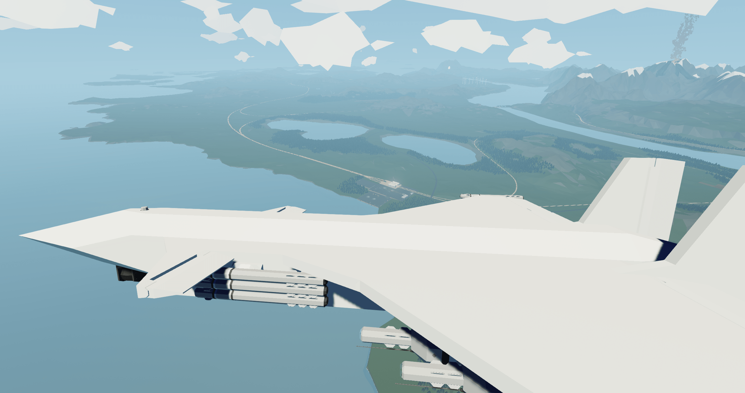
White Thunder – multi-purpose attack and reconnaissance UAV
Characteristics
- Length 20.5m
- Wingspan 14.25m
- Height 3.5m without landing gear
- Maximum speed ~135 meters per second
- Large fuel tank for very long operations
- The maximum effective range of application within a radius of +- 8km
- 21 mounts for weapons and more
- Advanced autopilot with semi-automatic target attack function
- Ability to integrate with third-party stationary weapons
Equipment
- 1 UAV White Thunder
- 1 White Thunder UAV control station
- 2 launchers with cruise missiles integrated into UVACS
Screens
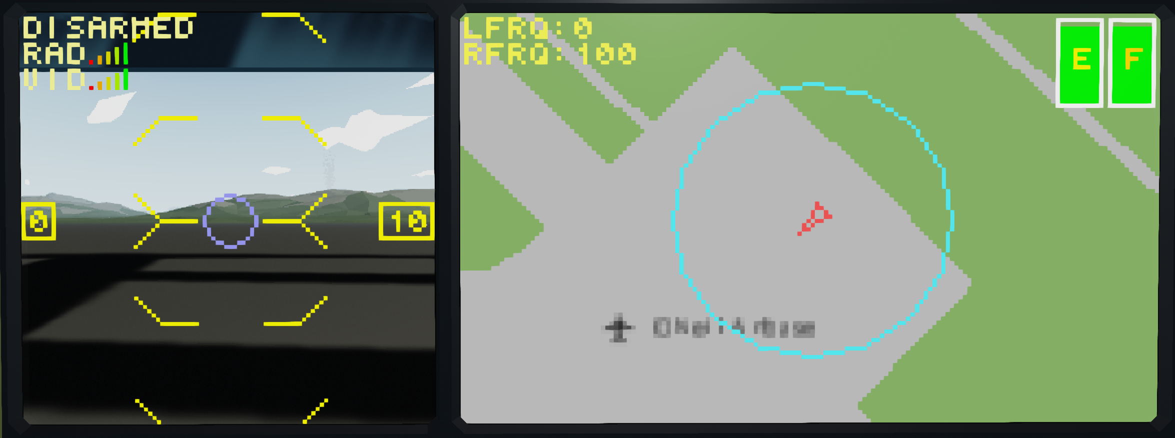
The interface of the remote UAV consists of 2 screens
Left Screen
The left screen is responsible for displaying one of two modes:
Operator mode
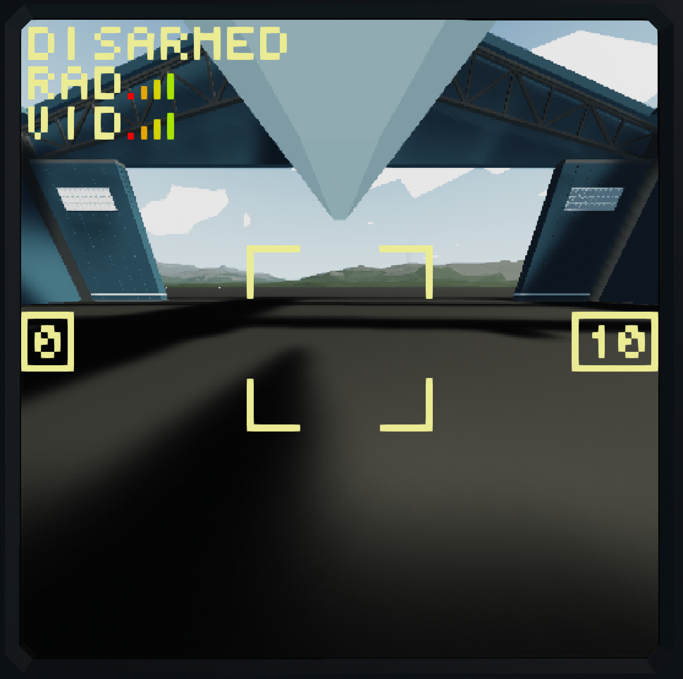
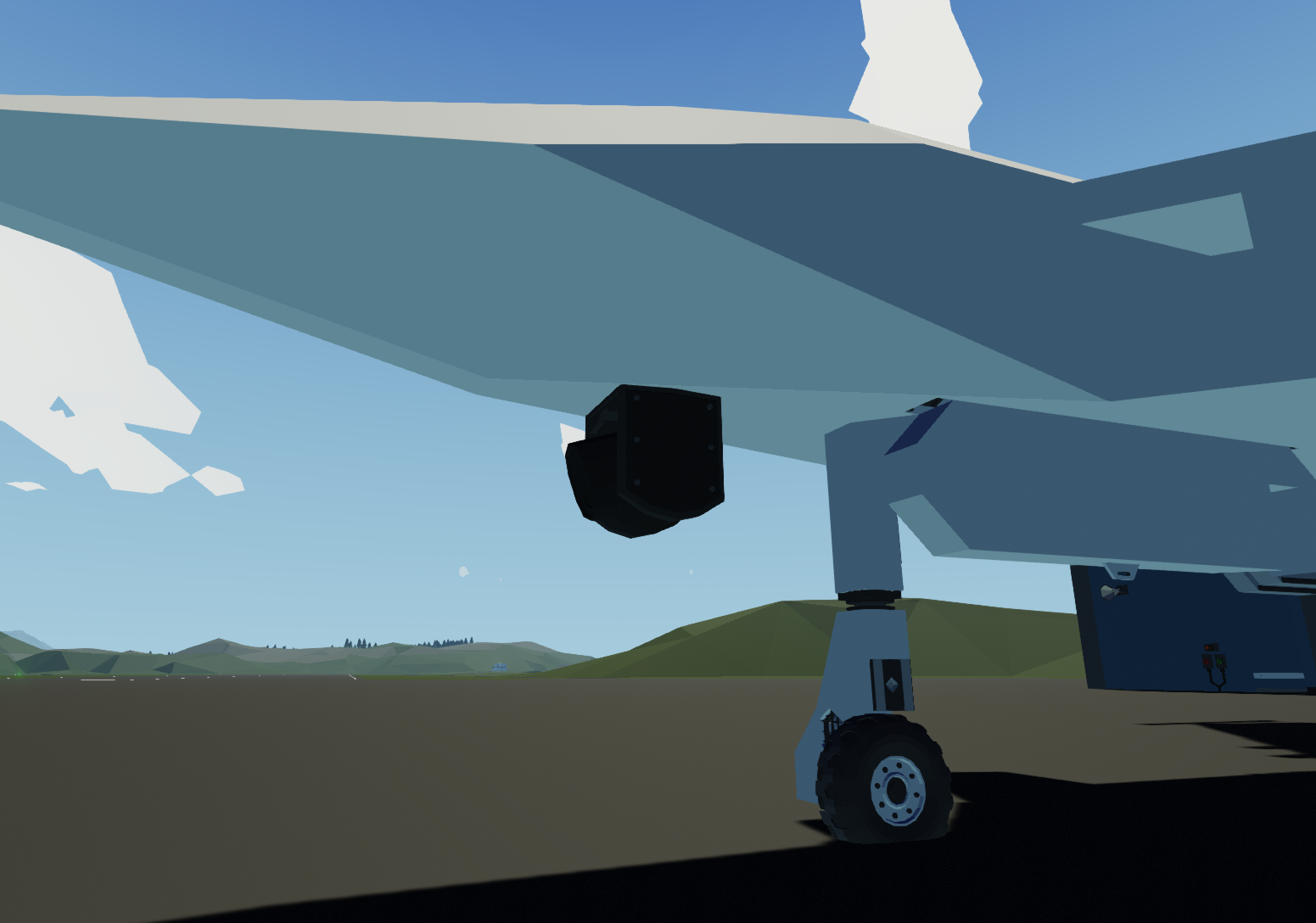
Allows you to view using a camera located in front of the front landing gear
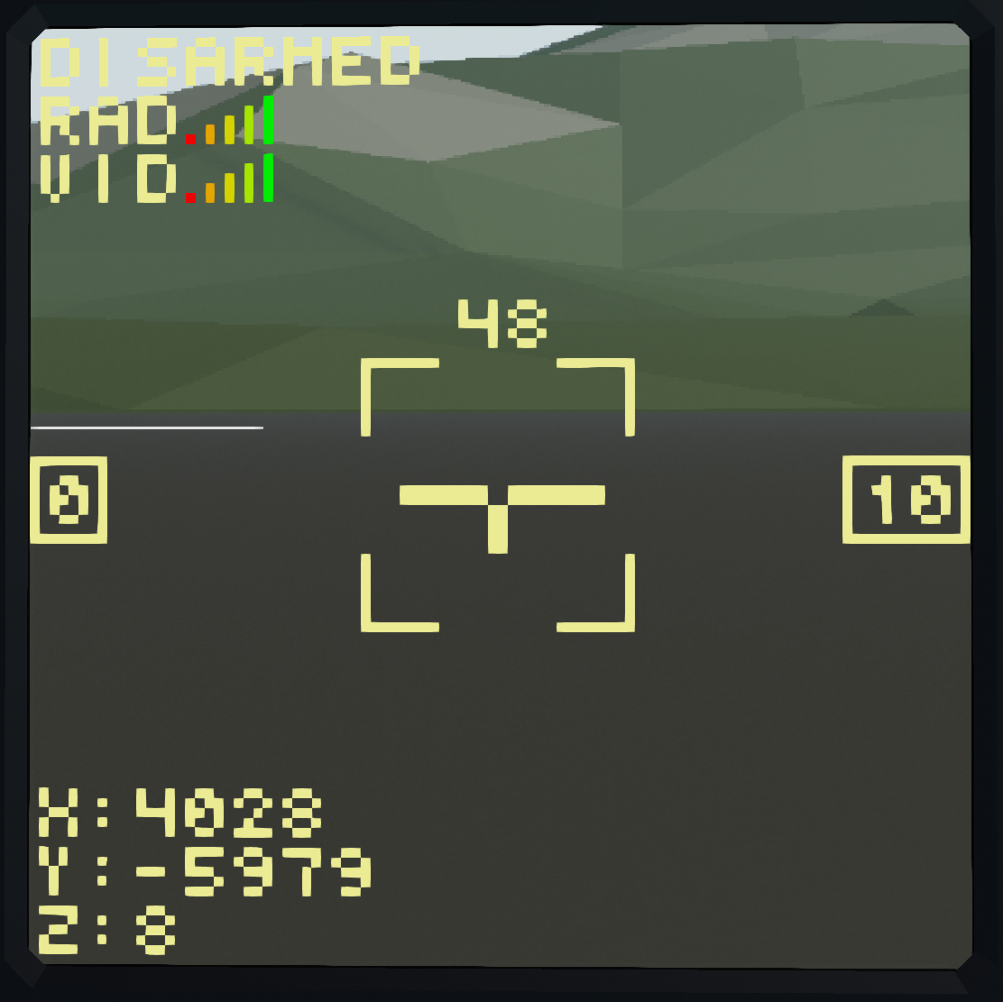
TOF is displayed in the center, when the lock mode is turned on, it will display a T-shaped figure for aiming
The number above the TOF is the laser distance to the target, if you enable track without a laser, this figure will not be displayed
The coordinates of the tracked target are displayed at the bottom left of the screen.
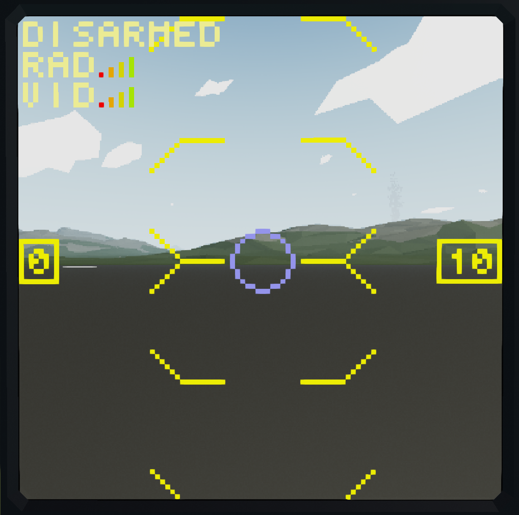
Pilot Mode
Puts the aircraft under the manual control of the pilot, allowing you to perform various maneuvers, or aim certain types of weapons
Provides an artificial horizon for orientation and a blue circle in the center to aid aiming
ATTENTION! Pilot mode temporarily disables the autopilot and when returning to operator mode, the UAV will automatically return to a circular route around the target
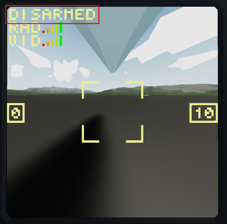
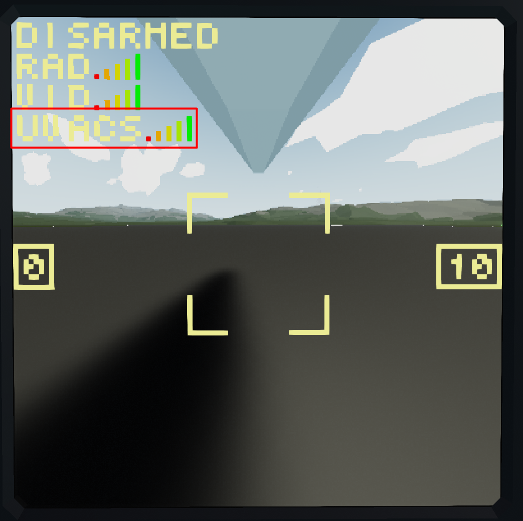
The screen also constantly displays the status of the AC in the upper left corner
Below it are indicators of the status of communication with the base station via video and radio channels, when the UVACS system is activated, the indicator of communication with the UVACS combat module will be displayed
Rectangles on the left and right side show the speed and pressure altitude of the UAV, respectively.
Right Screen
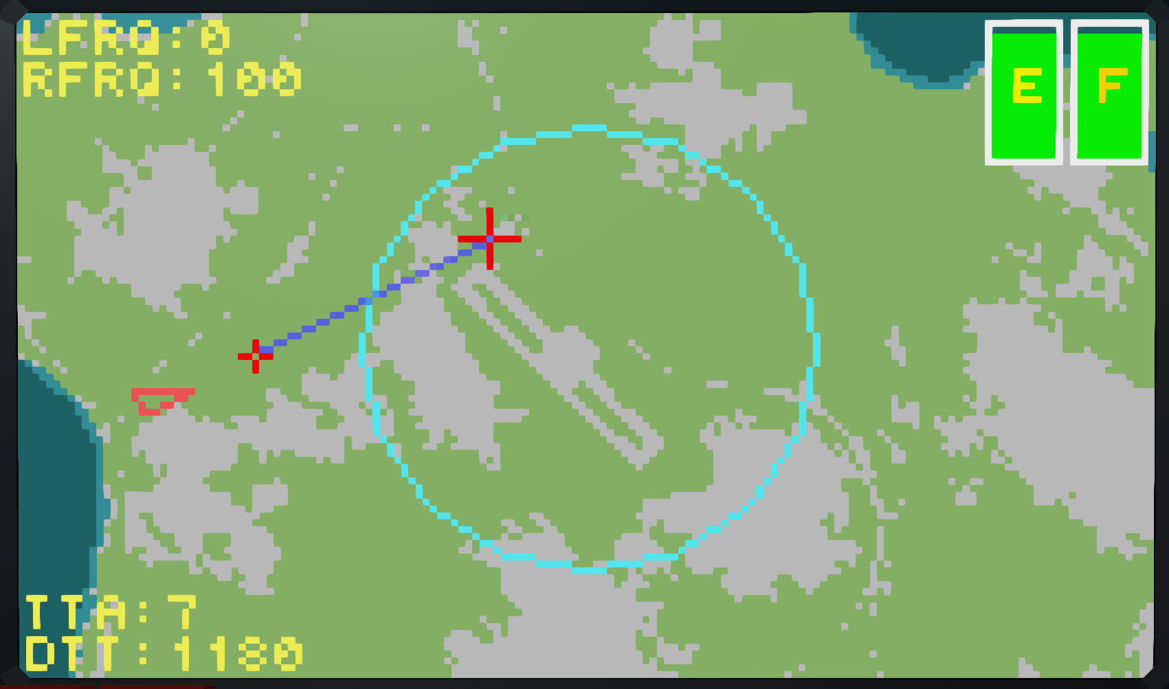
Map screen with extended functionality
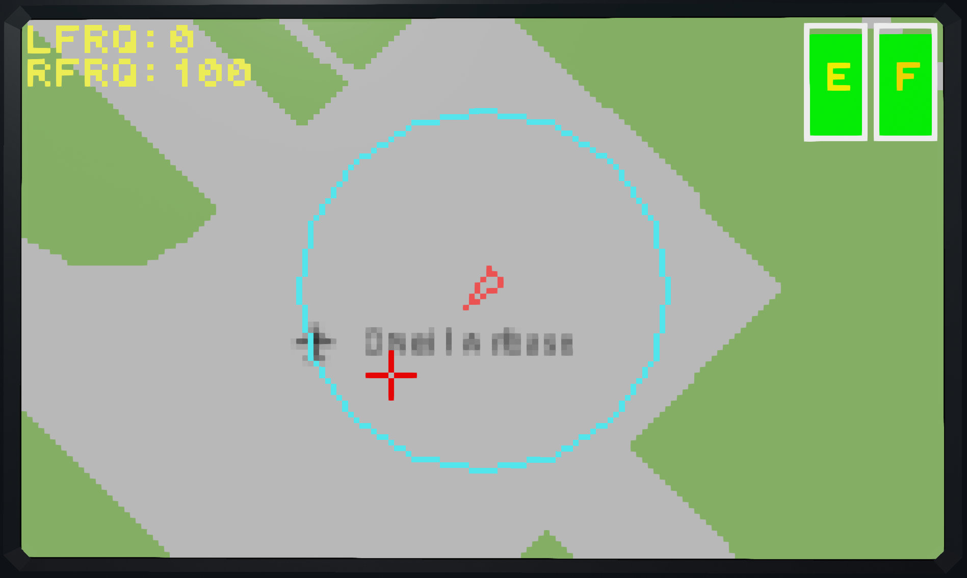
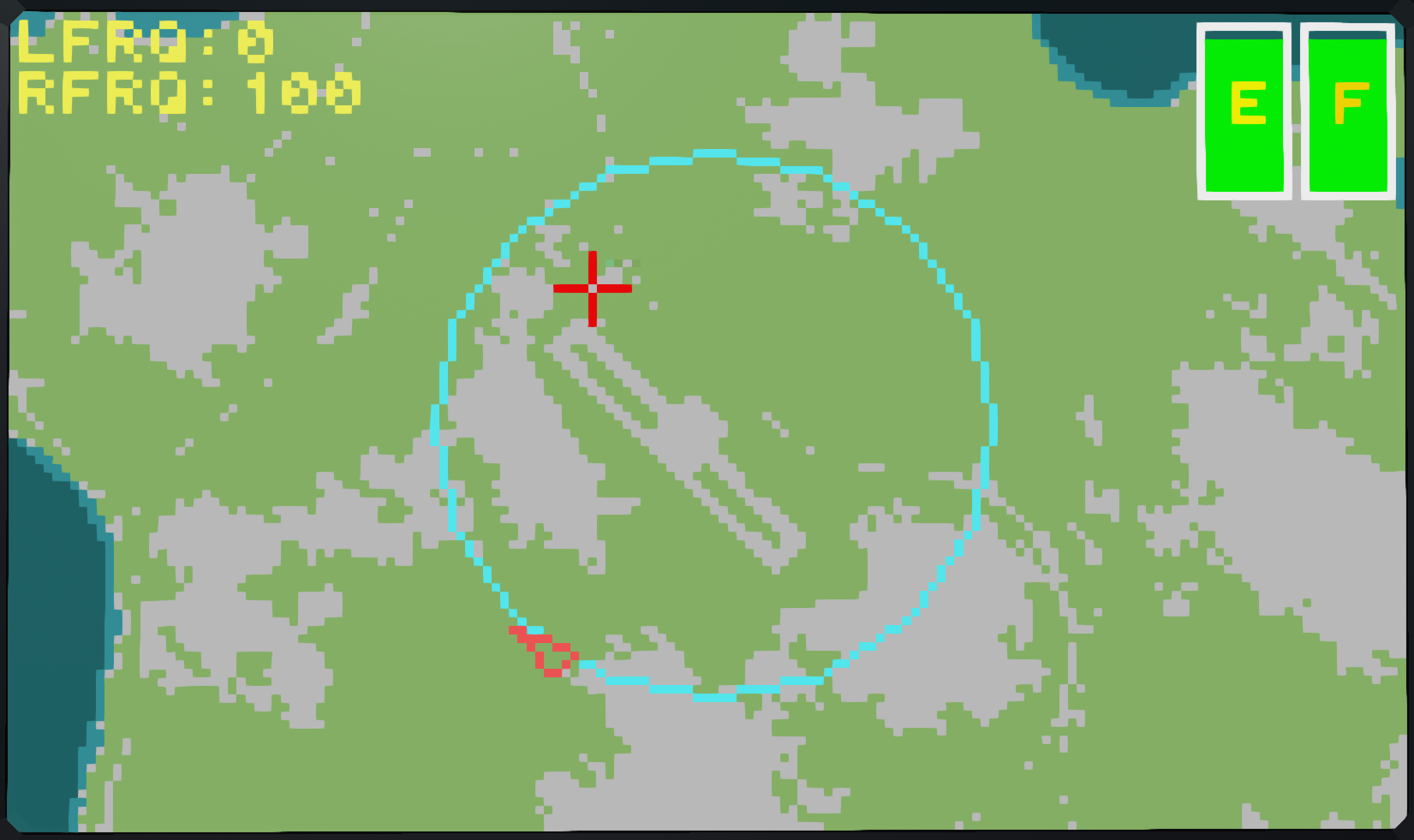
The indicators in the upper left corner are responsible for displaying frequencies for “smart” ammunition
In the upper right corner indicators of the battery charge and the amount of fuel in the tank
At low altitude (<50m), the map zooms in to make it easier for the UAV to maneuver on the runway as seen on the screen
At an altitude above 50 meters, the map switches to the “local” mode.
Blue ring – circling route
Red triangle – UAV controlled
When performing an attack, the position of the ammunition will be displayed with a small cross, the direction line from it to the target which is displayed with a large cross, in the lower left corner of the TTA and DTT for the target of the ammunition
Pilot’s seat
Pilot Mode
- A / D – roll
- W / S – pitch
- ← / → – yaw + turn the nose landing gear
- ↑ / ↓ – electric front wheel drive
Operator Mode
- A/D – camera yaw
- W / S – camera pitch
- ← / → – not used for operator mode
- ↑ / ↓ – increase/decrease camera view angle
General Buttons
- SPACE – apply the selected weapon/reset the selected gimbal
- 1 – activate UVACS
- 2 – change the radius of circling around the target
- 3 – change target height
- 4 – change the location of the circling target
- 5 – autopilot / operator mode
- 6 – manual control / pilot mode
Control panel
The remote control is divided into 5 zones:
- Green – control of key functions of the UAV, including setting frequencies for the operation of the UAV and UVACS, enabling communication with the UAV, turning on and controlling the power of the engine, extending or retracting the landing gear
- WFRQ – UAV operation frequency
- ACTIVATE – try to connect the UAV and turn on the control system
- ENGINE – turn on the engine
- ENGINE THROTLE – engine thrust
- LANDING GEAR – chassis
- Bright orange – Used to transmit the coordinates of the circling point to the UAV
The top panel is used to transmit the coordinates of the circling target, the single keypad is used to transmit the flight altitude, circling radius, radio and laser frequency.
- Dark orange – Responsible for flight control, namely the transmission of a certain type of target coordinates, and the transmission of a frequency for a laser or radio
- POS TYPE – type of transmitted data for changing the target of circling
- KEYBOARD – Keyboard
- SELF – control station
- LASOR TARGET – tracked laser target
KEYBOARD – Keyboard
SELF-control station
LASOR TARGET – tracked laser target
- KEYBOARD – Keyboard
- UPDATE LSOR FRQ – update camera laser frequency
- UPDATE AC FRQ – update weapon control system frequency
- ENGAGEMENT APPROACH – perform an approach maneuver, flying 1 km from the circling radius in the opposite direction from the center of the circling circle, then turn around and fly exactly to the center of the circle, then return to the circle
- POS TYPE – type of transmitted data for changing the target of circling
- Red – cocking and ammunition selection
- WEAPONS ARMED – indicator of bringing weapons into combat mode
- ARM – weapon cocking switch
- NEXT ARMAMENT – next armament
- PREVIOUS ARMAMENT – previous armament
- Blue – control of camera functions
- TRACK – tracking the target in the center of the RONC (tracks the sea if the laser is not turned on)
- LASOR – infrared laser for target illumination and tracking assistance
- IR – infrared camera mode for operating at night
- STAB – vertical and horizontal camera stabilization
General instructions for operating the UAV
Basic Preparation
- Inside the front landing gear compartment, enter the available frequency for UAV operation and press the FRQ SET button without holding it for a long time (subsequent holding is necessary to reset the frequency and block UAV control
- Move inside the UAV control station and enter the selected frequency into the WFRQ keyboard, turn the ACTIVATE flip switch to the ON position and wait for the CONNECTED indicator to turn on, if the indicator does not light up, check the UAV charge, if charge depleted, connect the power source and charge the UAV, if still indicator is off, repeat step 1
- Check the level of charge and fuel of the UAV, fuel should be more than 50%, and battery charge more than 80%, if lower, refuel and/or charge the UAV
- Check the presence of obstacles for the UAV to exit the runway, check the absence of a connected refueling hose and UAV power cord
- Return to the UAV remote control and switch to pilot mode to roll out onto the runway, the takeoff path must be more than 400m, otherwise, there is a very high chance that you will have to take off behind the runway
- Check the POS TYPE indicator with the number 2, if so then set the target[4], otherwise select the position type SELF
- Start the engine and pull the throttle lever to the maximum
- Start accelerating on the runway using the electric motor of the front landing gear
- At a speed of more than 50 m/s, start taking off from the runway by pulling the pitch toward you
- If the UAV starts to pick up speed, then switch to operator mode and lower the thrust lever to half
- Wait for the UAV to circle
- On exit to circle, turn the camera to the landing gear legs and start folding them, if one of the legs does not close, turn off and on the landing gear flip switch, if it does not help, repeat until it closes
- UAV is ready to work
Landing
- Set a target to circle SELF and move to a base station or available runway
- Start approaching the runway at a speed of no more than 80-90m/s by releasing the landing gear
- When approaching, turn off the engine (it is not necessary to touch the thrust lever, you will only lose useful time needed to control the aircraft)
- Gently touch the lane and wait for the UAV to stop
- Manually move the UAV to the park for rearming and refueling
UAV outboard armament attack
- Move to the target location and identify the target
- Enable toggle switches LASOR and TRACK on the camera control panel
- Direct the TOF with a crosshair at the target
- Set the circling target to the current location of the target by crosshairs using mode #3
- Press the ENGAGEMENT APPROACH button and wait for the UAV to turn towards the center of the circling zone
- “By eye” determining a good moment to launch, release the munition at the target
- Wait for the end of the attack route and the UAV to start circling around the target
Attack with UVACS system
- Prepare a combat unit for work
- Set the frequency of UVACS installation
- Move to the target location and identify the target
- Set UVACS frequency on UAV remote control
- Enable UVACS weapon application mode
- Enable LASOR and TRACK toggle switches on the camera control panel
- Direct the RONC with a crosshair at the target
- Perform an attack on the target
Attack with a cruise missile integrated into the UVACS system
- Prepare the combat unit for work (multiple systems are connected with 1 cable one to one, the cable is not needed in the opposite direction)
- Set the frequency of UVACS installation
- Move to the target location and identify the target
- Set UVACS frequency on UAV remote control
- Enable UVACS weapon application mode
- Enable LASOR and TRACK toggle switches on the camera control panel
- Direct the RONC with a crosshair at the target
- Perform an attack on the target
Abbreviations
- FRQ – FReQuency
- WFRQ – Work FReQuency
- RAD – RADio
- VID – VIDeo
- UVACS – UniVersal Armaments Control System
- LFRQ – Lasor FReQuency
- RFRQ – Radio FReQuency
- UTIL – UTILity (utility suspension)
- UGB – UnGuided Bomb
- LGB – Lasor Guided Bomb
- GPSGB – GPS Guided Bomb
- UR – Unguided/Unidentified Rocket
- RP – Rocket Pod
- LGR – Lasor Guided Rocket
- GPSGR – GPS Guided Rocket
- RGR – Radar Guided rocket
- UAV – Unmanned Aircraft
- WCS – Weapon Control System
- TOF – Target Orientation Frame
- TTA – Time To Arrival
- DTT – Distance To Target
- LSOR – LaSOR
- AC – Armament Control (UAV internal weapon control system)
Your time spent on reading Stormworks: Build and Rescue – Guide to White Thunder is greatly valued. This post was inspired by the fascinating work of VideoMaster.exe. If you have suggestions for improving this content, do share your thoughts in the comments. Enjoy your day, and remember to bookmark us for more updates and new articles!
- Check All Stormworks: Build and Rescue Posts List


Leave a Reply