In this guide, we’ll be creating a shader that simulates a monitor display, complete with RGB pixels, the ability to set its resolution and blend between the source input to the RGB pixel display.
If you’re new to creating shaders, please check out the introduction guide first right here!
Shader Scope
The shader we want to make is actually pretty simple – we “pixelate” the input texture, and when we get close enough to it, we’ll blend into a version that replaces every pixel we plotted with the three elementary colors – Red, Green and Blue, all shining in different strengths according to the input texture’s color to create the same illusion that the monitor you’re currently staring at is achieving.
So we can split this shader into 3 points of interests:
- Pixelation – We take the input image and pixelate it to fit out target resolution.
- RGB Pixels – Creating the RGB pixel layer.
- Distance – Getting the distance from the viewer to the plane to determine which layer to display.
In the end, you should have a shader that looks like this (apologies for the low quality gifs, Steam won’t allow media bigger than 2MB!)
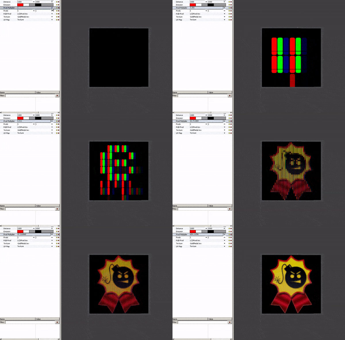
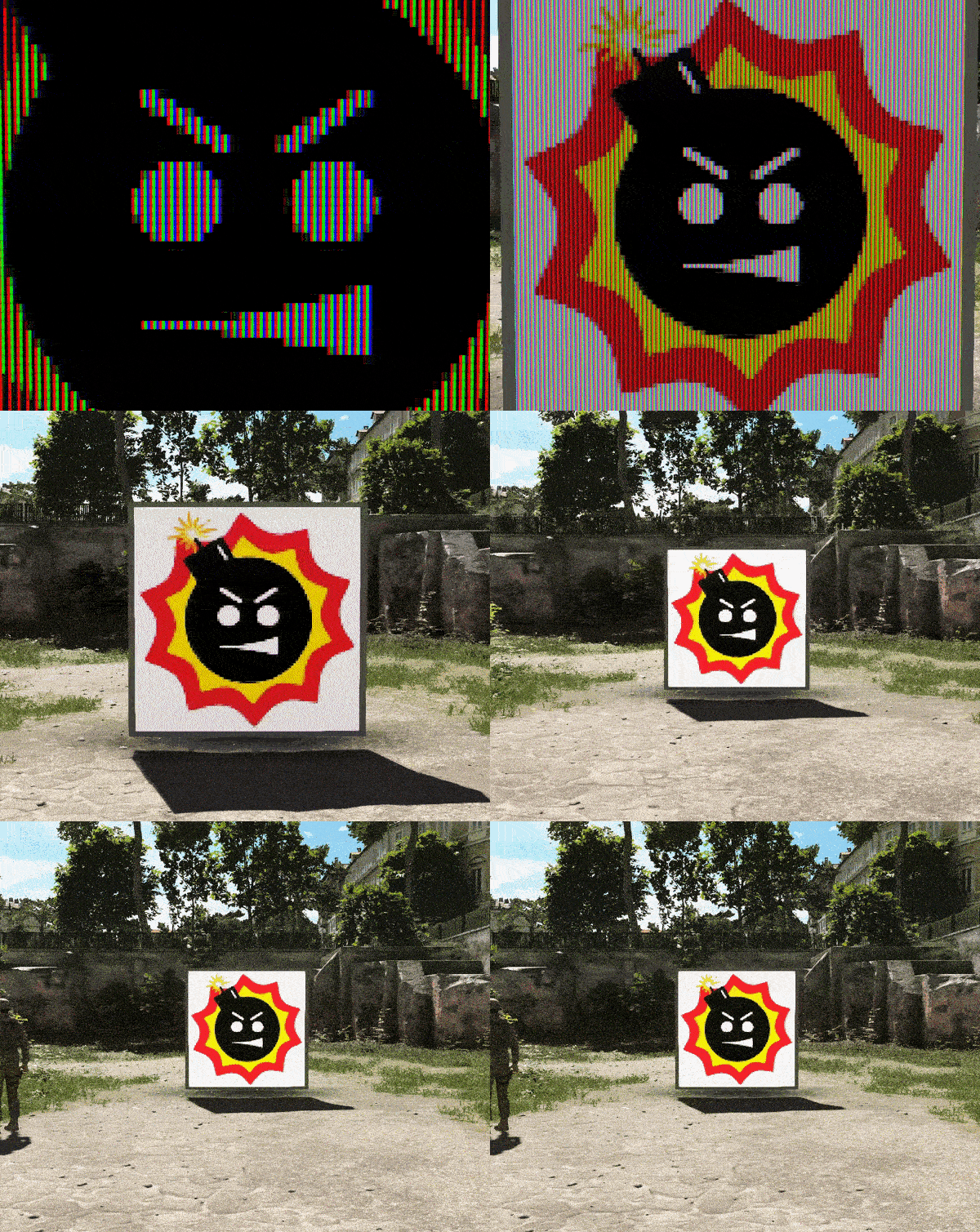
A note before we start – in my screenshots, you may see additional connections in nodes that I did not cover or instruct to create – do not be alarmed, I’m taking screenshots from the finished graph and those connections are explained later. You’ll understand what’s relevant and what’s not.
Getting Started
Before we dive into the juicy parts, let’s first set up our core.
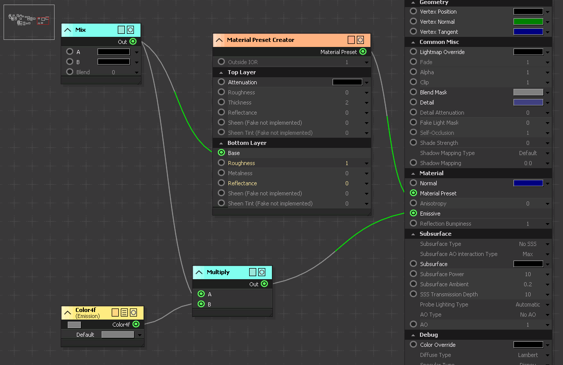
Grab a PBR2 Shader node to use as our master node, as well as a Material Preset Creator, and connect it to PBR2’s Material Preset.
Then we’re going to grab a “Mix” node, and we’ll plug it into the Material Preset Creator’s Base Color. If you’re unfamiliar with what the Mix node does, I’ll explain in a bit. But while we’re on a roll here, let’s also set up Emissive – so grab a Color4f node (since we need an HDR color for emission!), name it (“Emission”), give it a default value of H0S0V1, and finally, multiply it with the Mix node we’ve created earlier to ensure we actually light up our texture and are not just creating a color overlay. Then plug it into PBR2’s Emissive.
If your graph looks like this so far, you have done well!
The Mix node (or alternatively, Lerp) takes two inputs (A, B) and interpolates between them according to a third input (T), that is clamped between 0 and 1. So, for example, if T equals to 0, the returning result would be equal to input A. If T equals to 1, the result would be equal to B. If T equals to 0.5, the result would be the midpoint between A and B.
You can probably see where this is going already – input A will be our RGB pixel overlay. Input B will be our base texture. Input T will be the distance.
Pixelation
Now starts the fun part!
To achieve the pixelation effect, we’re going to want distort the UV’s. This is a bit hacky, because we can’t rely on good old “Modify UV Map” for this task, and in fact, the only node I’ve found so far capable of performing it would be “Backface UV”.
So let’s grab “Stream UVMap”, name it, and also grab “Backface UV” and plug our stream into it.
Now I’ll be completely honest, I am not sure the technical reason for it, if even intended, but Backface UV seems to only get half of the UVMap, so you might end up with something that looks like this:
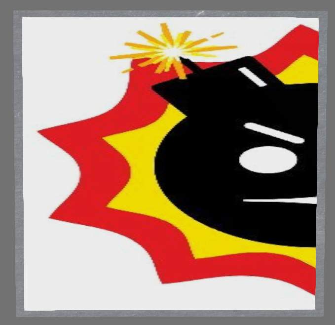
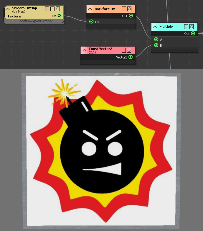
Luckily, this is an easy fix – we just multiply the X of our UV coordinates by 2! Grab a Const Vector2, name it “2,1” to set its value, and multiply it with the Backface UV. Now our UV coordinates are fine and we have full control over them.. hehe.
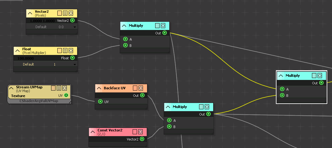
Now let’s get to pixelatin’. Get a Vector2 node, and name it “Pixels” or “Resolution”, whichever you prefer – this will be our pixel count. Just to make editing easier on myself, I’ve also created a Float called “Pixel Multiplier”, which I multiply with the Vector2 – it multiplies the entire resolution.
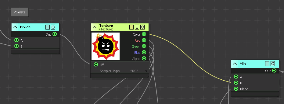
We’ll then want to multiply our UV coordinates with the pixel count, so your graph should look something like this:
At this point, I would want to “Round” our multiplication results to the nearest integer so we’re only left with whole numbers, but sadly, SED doesn’t have a Round node.. but what it does have are “Floor” and “Ceil” nodes, which return the biggest or smallest integer value. So for example, flooring “1.5” will return 1, and ceiling “1.5” will return 2. Get it? Floor and ceiling?
We can create our own round functionality with a simple trick of just adding 0.5 to our value and flooring it. For example, the rounded value of 1.25 would be 1, but the rounded value of 1.75 would be 2. Apply that to our functionality: floor(1.25 + 0.5) = 1, floor(1.75 + 0.5) = 2. It’s round!
So let’s create a Const Float and give it a value of “0.5”. Add it with our multiplication, and then plug it into a “Floor” node. Now the only thing left is to divide our rounded multiplication back again with our pixel count, and we’ve created a pixelation effect!
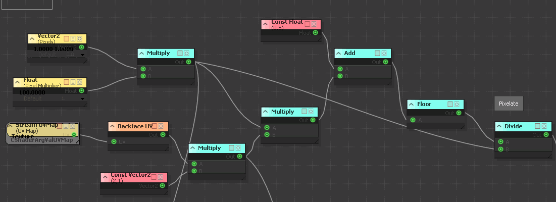
So this is our UV distortion formula. Now let’s create a Texture node (which will be our base texture), and plug what we’ve made into its UV slot. Then, plug the result of the Texture node into our Mix node’s B input, and specifically B, because this is the result we want to display the farther away we are from the plane.
Congrats, you’re 1/3 of the way!
RGB Pixels
My personal favorite – creating those screen pixels that consist of RGB lights, all shining in different strengths to create different colors.
First off, you’ll need to download this texture and import it into the game. Go ahead, it’s on the house. Royalty free!
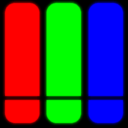
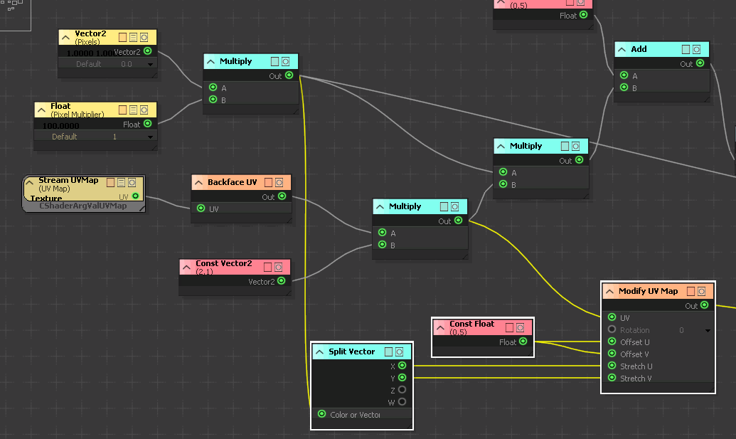
Now let’s actually start taking care of UVing these guys. Unlike our base texture, we don’t need to pixelate those guys – they’re the pixels themselves! Instead, we want to fill every pixel in our screen with them. And for this, we can easily use a “Modify UV Map” node, so grab one!
Our Stretch U and Stretch V values will be equal to the amount of pixels we’ve defined, so let’s grab a Split Vector node, plug our pixels value into it, and then distribute it – X to U, Y to V.
Remember how we’re rounding our UV coordinates? This means our offset is going to be off by that same 0.5 we’re adding, and since we want to perfectly align our pixels with the image, we’ll have to plug a constant value of 0.5 to Offset U and Offset V of our Modify UV Map.
That’s basically all we need for the RGB Pixels’ UVs!
Now let’s create another Texture node, and this one will be the RGB Pixel texture we downloaded earlier. Sadly SED doesn’t have a way to set a default texture value, so you’ll have to manually input it.
Once you’ve plugged the Modify UV Map node we constructed earlier into the Texture’s UV slot, we can start controlling the strength of these lights. And the way we do it is actually pretty straightforward:
Multiply the red channel of our base texture with the red channel of our RGB pixel texture, multiply green channel of base with green channel of RGB pixel, and same for blue. So if pixel in your texture has an RGB value of (1,0,0), in our RGB pixel, that is going to correspond to the red light being fully lit, and the other two being fully dark.
So let’s create 3 Multiply nodes, and multiply each channel of each texture together – red with red, green with green, and blue with blue. Then, we’re going to grab a Combine Vector node to reconstruct the results. Why Combine and not Add? Because we’re not trying to add these values together! We want the values as is, just living together happily under one vector.
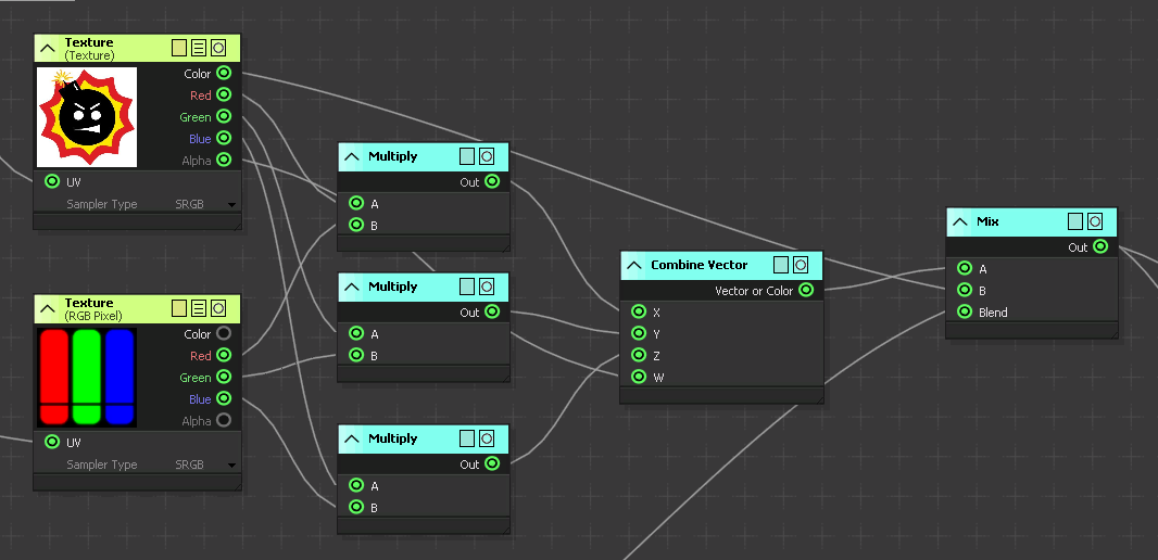
Plug the Combine results into the A slot of our Mix, and voila – 2/3 done!
Distance
One last hurdle to go through – the value that will determine how to blend the two inputs we’ve created.
Let’s start with a “Distance To Plane” node – this is the core node we need to be able to get the distance from the viewer to the plane. However, as you’ll see, we need to feed it some info first.
For “Plane Origin”, we’ll want to use “Vertex Position” node – this node contains information about the position of the vertices.
For “Plane Normal”, we’ll want to use “Vertex Normal” node – this node contains information about the normals of the vertices.
And finally, for “World Position”, we’ll want to use “SV_ViewPos” – this node contains information about our viewing position.
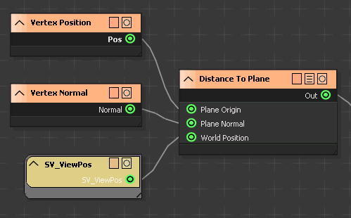
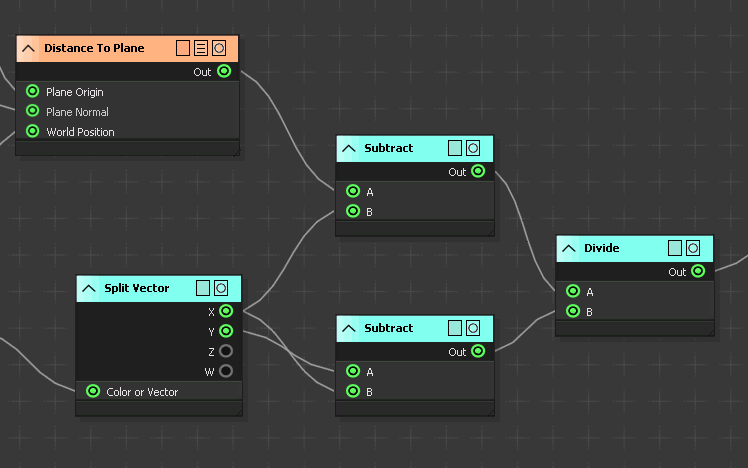
So far so good, but we want to be able to control the distance values. Let’s create a Vector2 node and call it “Distance” – the min value will correspond to our “A” (the pixel overlay), and the max value will correspond to “B” (the base texture). If our distance is inbetween, the inputs will interpolate.
Add a Split Vector node and plug the Vector2 node we made into it. We’re going to add two Subtract nodes – in the first one, we’ll subtract our Distance To Plane with the min value of our own Distance node. In the second one, we’ll subtract the max value of our Distance node with the min value. And then – we’ll divide those two subtractions together.
nbsp;
We have our Distance set up, but we need to make sure the values are clamped between 0 and 1, and not overflowing (remember how T of Mix is clamped between 0 and 1?). We could use a Clamp node for this, but there is already a node that answers specifically that requirements – “Saturate”. It returns the input value clamped between exactly 0 and 1.
So grab a Saturate node, plug our division into it, and finally, plug it into “Blend” of our Mix node.
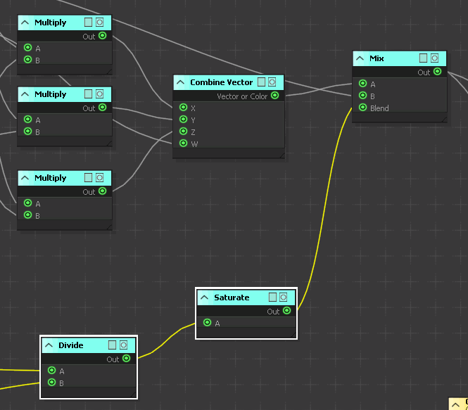
If followed correctly, your monitor shader should now be functional! Play around with the settings and see how it suits you. There are plenty of ways to improve this shader still, but I will leave the rest in your creative hands. 🙂
Hope you enjoy the post for Serious Sam 4 Node Graph Examples – Monitor Shader, If you think we should update the post or something is wrong please let us know via comment and we will fix it how fast as possible! Thank you and have a great day!
- Check All Serious Sam 4 Posts List


Leave a Reply