This is a step-by-step guide to implement a ship into Nebulous. Currently the main hurdle to overcome when creating new content for the game is the limited documentation scattered on the Discord server. This guide aims to gather all the currently available resources and provide a lifeline to prospecting modders.
Be aware that the game is still in development and the modding scene in its infancy. Some information in this guide may become outdated.
INTRODUCTION
Before starting, I will advise any prospecting modder to begin with a small ship. The initial cliff when modding Nebulous is quite intense and the game’s requirements sometimes very peculiar. It is not unlikely that you will have to redo your first ship from scratch once all the information start to click into place (just like I had to). While I am not convinced that you should go as barebone as implementing a cube with thrusters first, starting with a huge Battleship will add an unnecessary load on your shoulders.
I would also advise to skim over at least the entire modelling section of this guide first, as opposed to following it step by step, to have some idea of what the result of that part should be.
Official Guides
Stephmo, the dev team member responsible for the ship models, wrote a short but very informative primer – [itch.io]” rel=”nofollow noopener”>short but very informative primer – [itch.io] about the requirements for the game when it comes to the modelling. The points that are of particular importance are the need to share UVs across all Level Of Details and the collider mesh (UV coordinates are used by the game to not only display damage but also efficiently calculate the state of the armor at any given point) as well as how ship models are divided into sections to maintain texture density.
On Unity’s side, there is an Official Modding Guide to setup your Unity project – [steamcommunity.com]” rel=”nofollow noopener”>Official Modding Guide to setup your Unity project – [steamcommunity.com] that you will have to go through.
About Ship Designs
There are a few things to keep in mind when designing a ship for Nebulous:
- The game does not support hollow ships. For example, if a tandem-hull catamaran ship is hit from the side on the left hull by a railgun sabot, the projectile will exit from the right hull instead of exiting the left hull then penetrating the right hull through the gap. That may or may not something that you are willing to live with, but be aware of this behavior.
- The damage model shines when ships have large uninterrupted smooth hulls sections. Any seam in the texture will also be a seam in the damage decals. Additionally, the collision model requires convex shapes. Too many concave angles will have a significant impact on performances as well as making the collision model increasingly complex to setup. A box is the perfect Nebulous ship design! Using normal maps instead of geometry to convey minute details is strongly advised.
- While it is not strictly required, the color of the bridge lights is used in the game to indicate a loss of power. Having an easily identifiable element to convey that information is therefore advised. It is also a convenient way to indicate the scale of the ships across hull sizes and factions.
- Ships do require maneuvering thrusters for every translation and rotation axis. They can be force field technobabble mac guffins that do not have a visual effect, but the engine will require game objects to exert forces and those objects will have to show up in the Damage Control Board.
- Radar panels can cover any number or “quadrant” as defined by all three of “right/left”, “up/down”, and “front/back” directions (+/-X, +/-Y, +/-Z) for a total of 8 sectors. That means you cannot have a “left, right, top, down” layout without overlaps.
Resources
To ease one’s first steps into modding Nebulous, I have gathered a few resources together – [patreon.com] in a convenient download.
As reference for modelling your ships, you can either extract the models from the game files, or use the rough mockups I created.
I also bundled all the assets you will need to implement your ships in the game. That includes everything mandatory made available by the devs (shaders, DC board prefabs) but also a lot of things I had to create.
Among those assets are my engine sounds, and visual effects for the engines. Those being quite time consuming to create, I feel making them available can greatly help new modders. On the other hand, please consider those elements as part of the identity of my Prism mod, therefore they are meant to be used as placeholders in your own creations, or at least significantly modified before release. Thank you in advance.
Acknowledgement
Big thanks to AGM-114 and Ancient on Discord that spent so much time helping me implement my first ship. This guide would not exist without their prior work figuring out all that stuff!
And obviously thanks to Mazer for helping too and making many assets available.
MODELLING
I will try to keep this section fairly software-agnostic, but I am assuming that readers of this guide know their way around modelling, UV unfolding and texturing. This expands on Stephmo’s guide thus you should read his first.
Rough Block
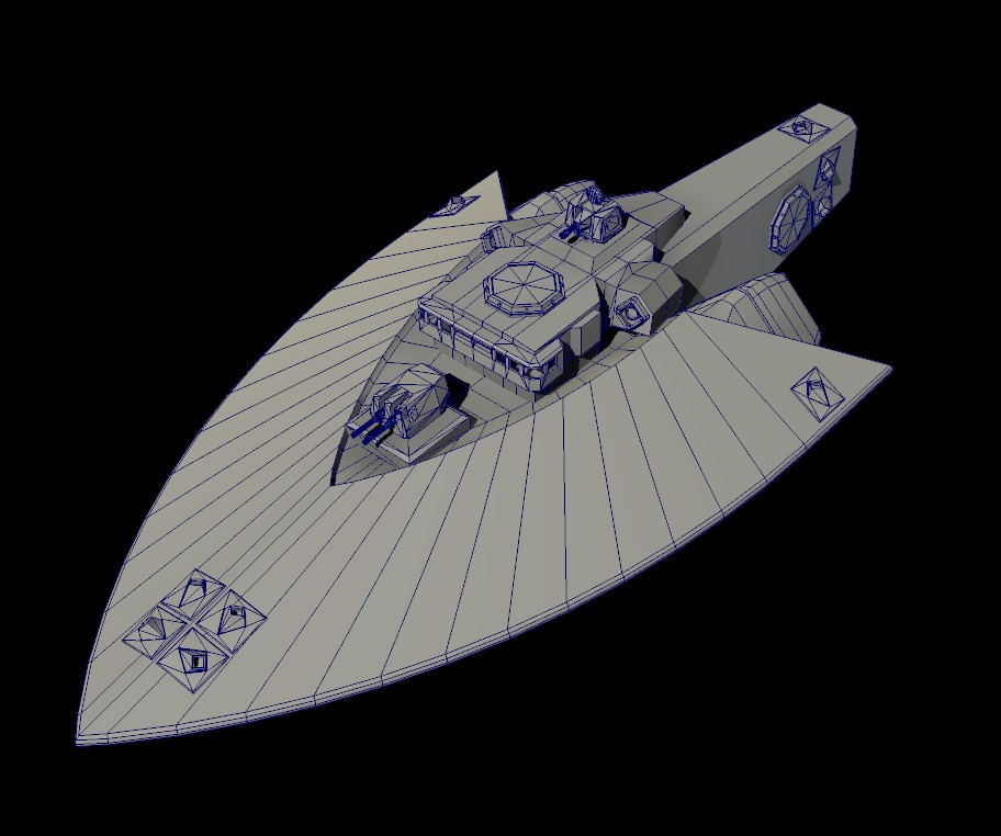
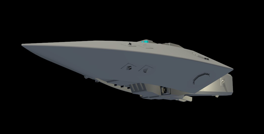
When working on a model, I always start with a rough volume blocking to plan my geometry. I heavily rely on kitbashing parts from other models to both work faster, but also to scatter recurring elements across my ship lineup to build a coherent design language.
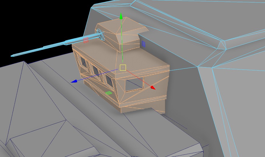
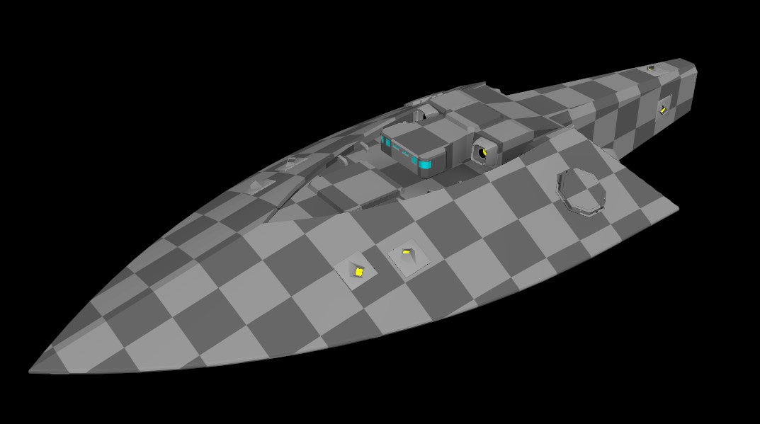
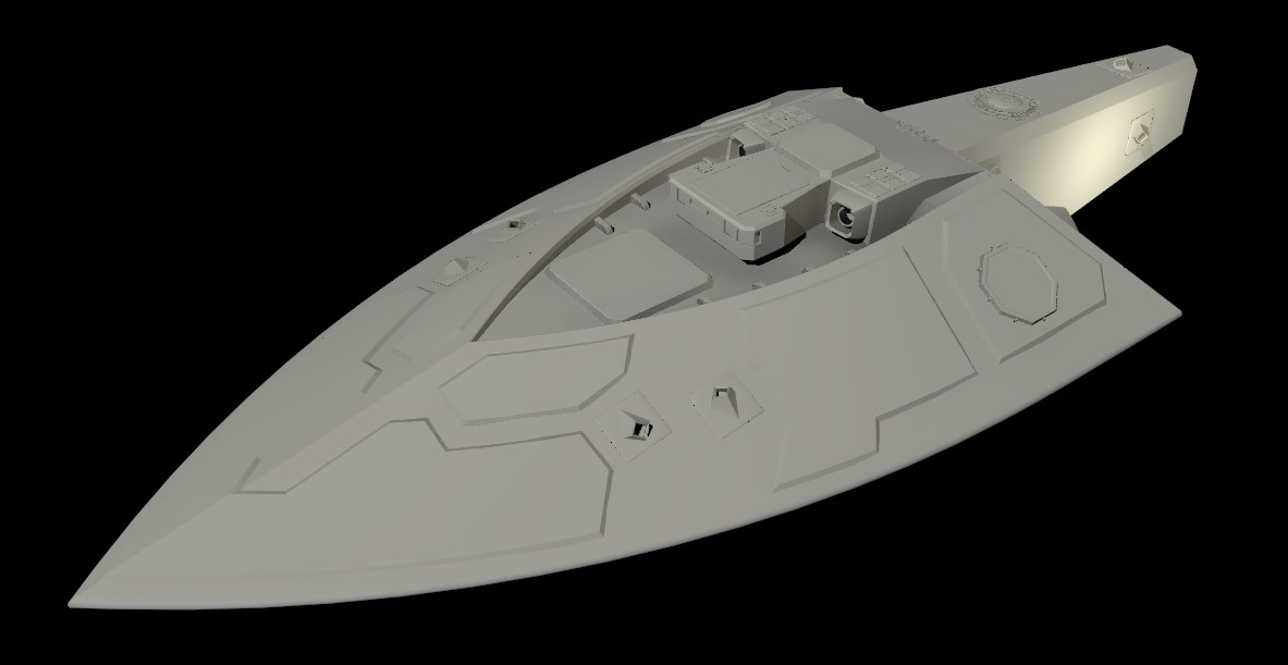
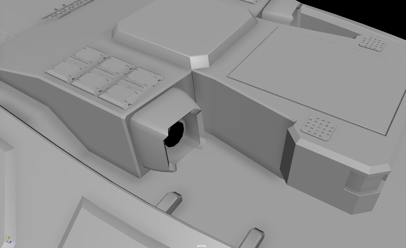
The goal here is to quickly iterate on the overall shape to get the right proportions and flow, as well as defining weapons, radar panels, and thrusters emplacements. I can already notice areas that will need refining such as this very complex geometry near the engines that will be a nightmare to simplify for the collider.
Level Of Detail 0
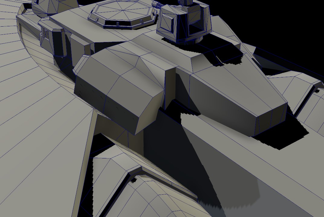
Some modeler like to start from the simplest shape and work their details up. Given the requirements regarding the UVs consistency, I personally prefer to start with the model that will have the highest details in-game, then simplify it down (as well as detailing it for normal map baking).
There I massively simplified the complex section of the ship down to a few angles while keeping the overall flow of the hull:
A couple of remarks:
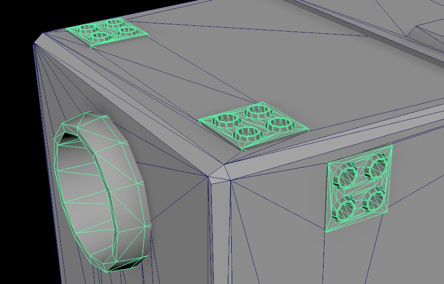
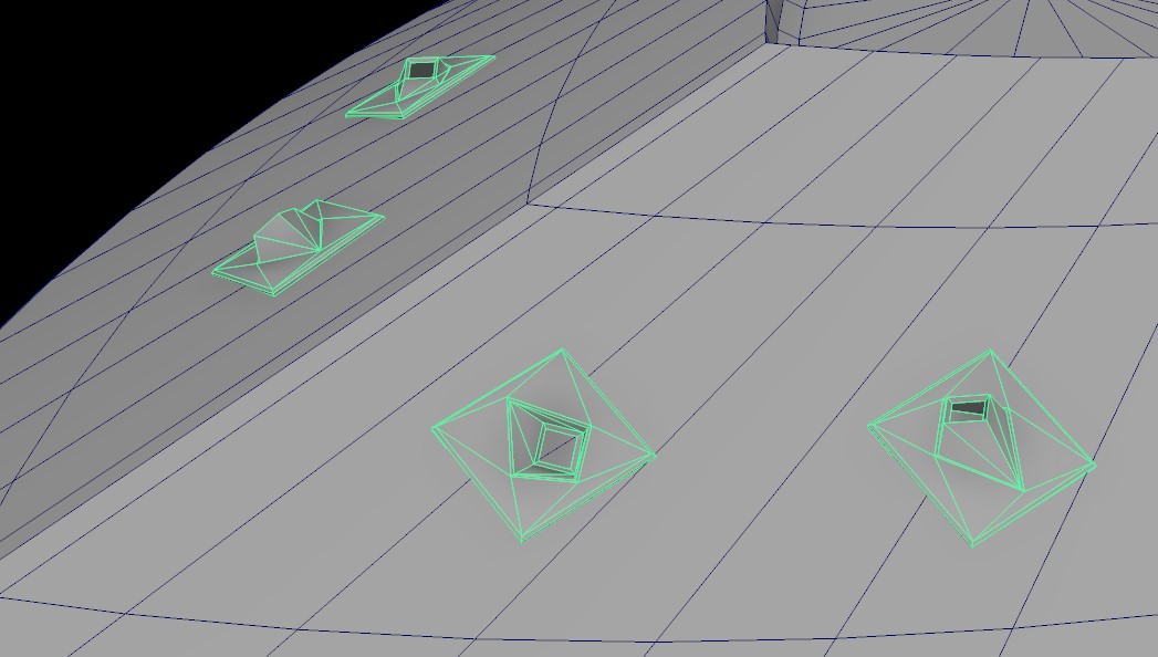
- While polygon count should not be entirely ignored, the game is fairly forgiving on that front. keeping a few extra polygons that will make your life easier while texturing or when placing components within Unity is not a deal breaker. For example I have some extra edges to find the center point on the weapon platforms so that I can snap the mounts on them.
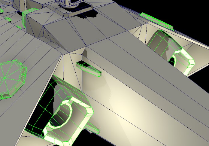
- On that front, the biggest contributors to poly count in vanilla between LOD0 and 1 are the attitude thrusters. Having a simpler design for those on your ship can easily shaves thousands of polys that can be reinvested elsewhere:
- While you do not need to make an airtight model for this step, you will have to for the collision model. That is why I already try to avoid having meshes that penetrate within others for volumes that will be part of that collision model, and try instead to have everything merged properly. See this example on the vanilla frigate:
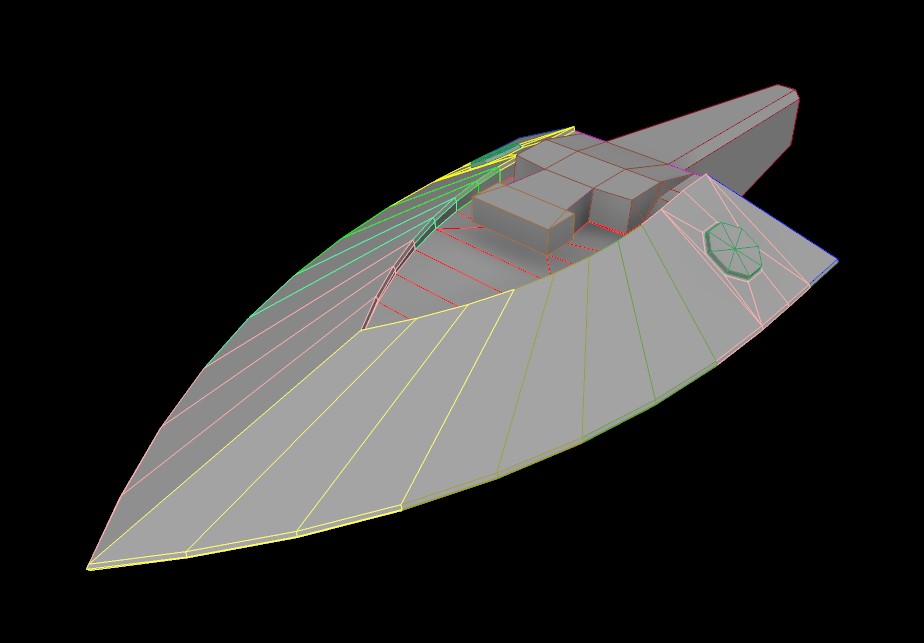
- Keep in mind that you will need to splice your model into convex volumes for the collider. You will need well placed edges to cut through across the UVs and different detail levels.
UVs and Hull Sections
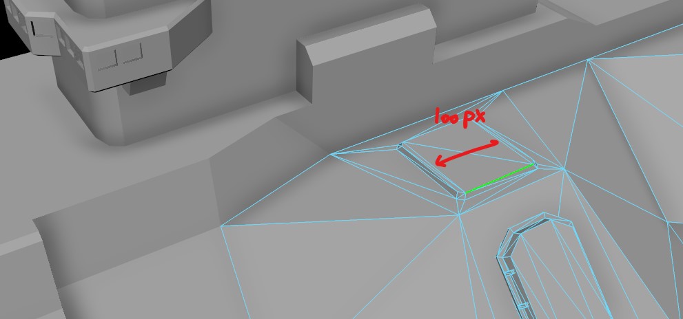
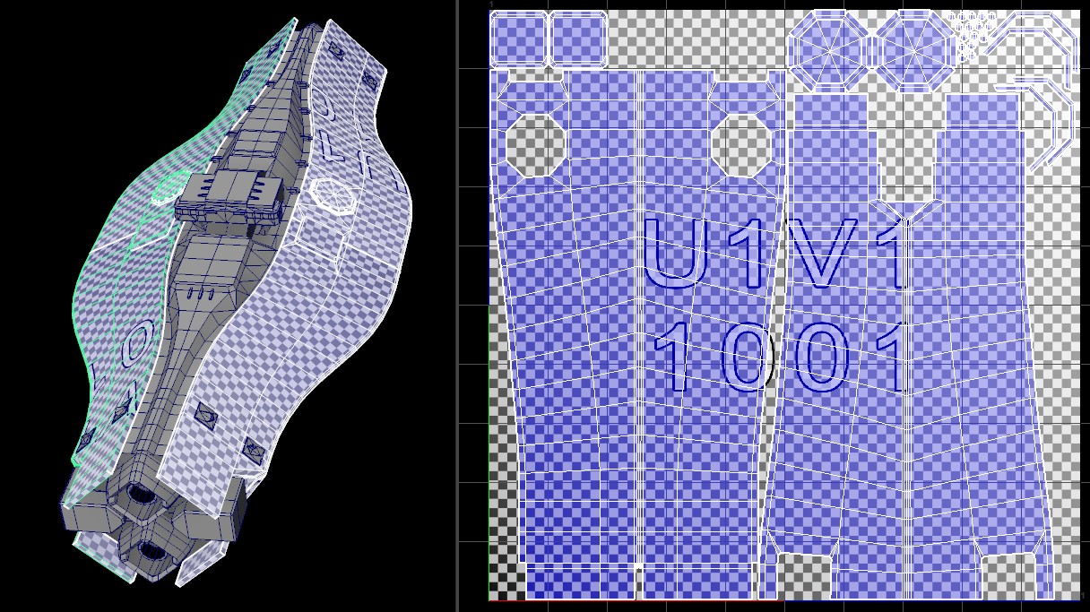
All the textures maps for ships are either 1024×1024 or 2048×2048. To maintain the pixel density across ship sizes, the models are cut into segments. From 2 for the corvette to 6 for the battleship. The engines and thrusters are always separate objects apart from the hull. Additionally, the glowing engines throats and the windows are required as their own separate objects. The texture density for the vanilla ships is roughly 2 pixels per unit, which translate for example to 100 pixels for the edge of the class 1 weapon mount platform:
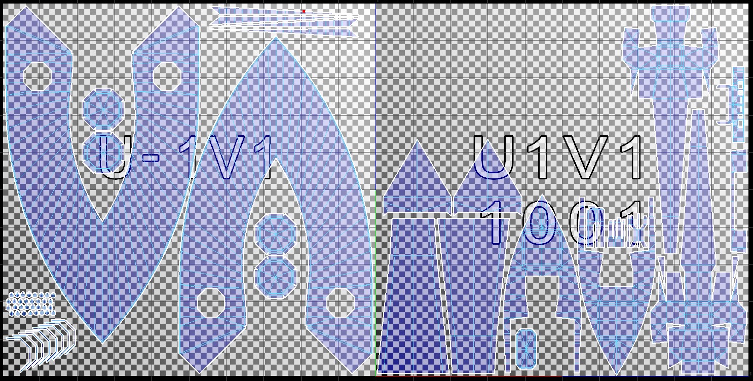
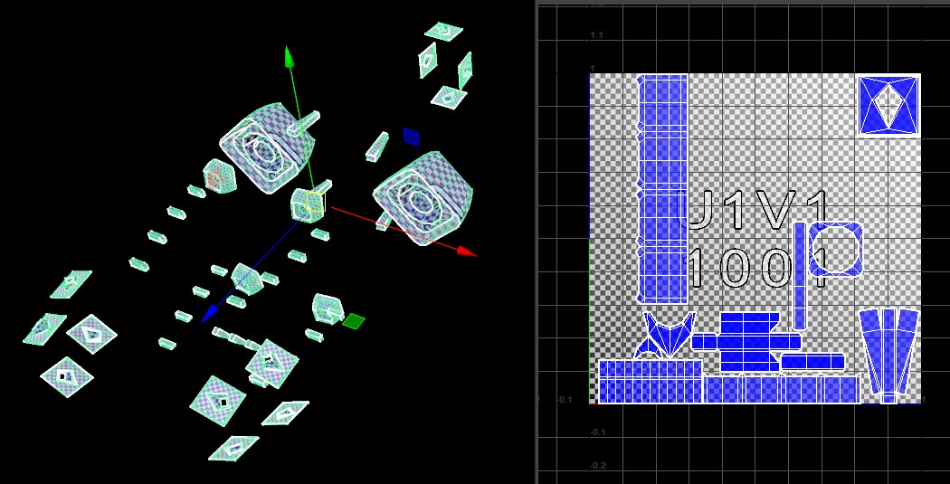
Personally, I found it most efficient to unfold the UVs and pack them before cutting the model. That way I can avoid awkward merges if I miscalculated the mapped areas, or add edges when a seam is needed:
(That big empty area in the right UV map may come in handy when I get around to make escape pods) Those familiar with my mod will notice that I gathered all the hull parts that get custom colors on a single map, meaning I only have one paint mask texture to make and to have loaded in the game.
Given that the game uses the UVs and an internal texture to model the damage received to the armor, you cannot have overlapping UVs on polys that will receive damage decals part of the same hull section. However, you can have overlapping UVs on small details that will not be part of the collision model such as antennas and decorative struts.
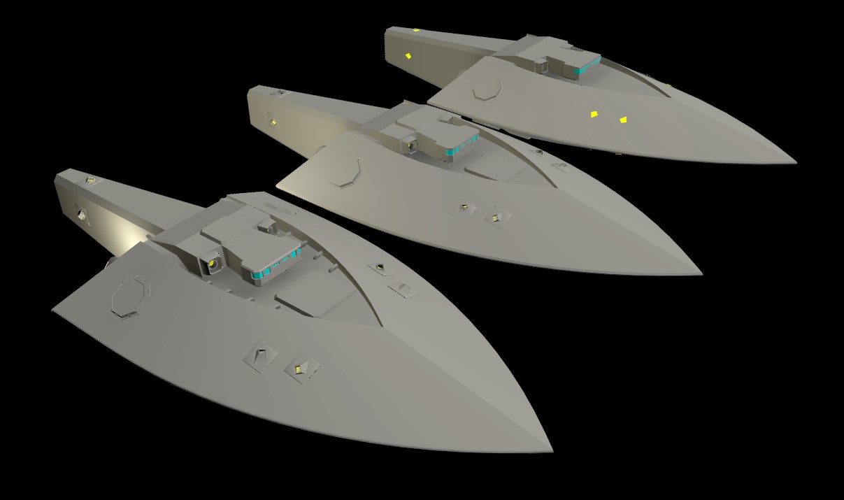
If you go even further, you can have the same texture for two halves of a symmetrical model as long as those halves are their own separate parts with each their own shader/damage model. I notably used that on my destroyer-sized ship where both sides of the armor are the same model rotated 180 degrees along the ship spine:
Given that the engines/thrusters do not receive damage decals, they can share overlapping UVs when duplicated. I used that to my advantage by having “standardized” thrusters and engines sharing a single set of texture maps across my entire faction, along some tiny repeating details such as trusses only visible on the LOD0:
Remember that the damage model work best when there are fewer cuts to the UVs.
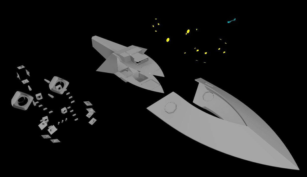
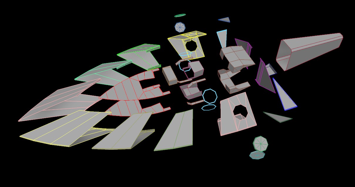
Once I’m happy with the UVs I can slice my model into the required parts:
- engines glow (yellow)
- windows (blue)
- engines+thrusters
- front armor segment
- rear hull segment
LOD 1 & 2
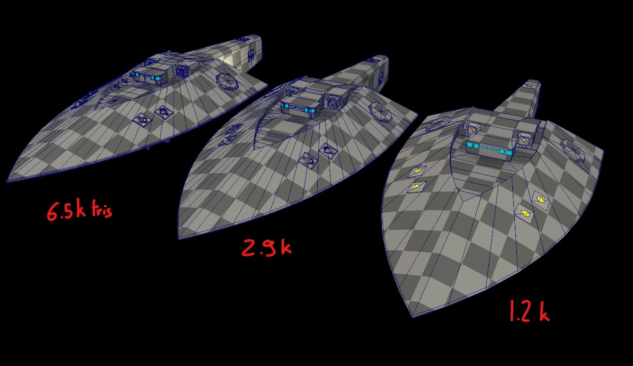
Since the UVs are done, simplifying the model is now fairly easy. The vanilla poly counts should be from 8-10k for the LOD0 down to about 2-3 k for the LOD1 and under 1K for the LOD2. As mentioned before, those numbers are not hard limits as the poly count for the visual models is not a bottleneck.
The easiest places to simplify are the bridge windows insets, the engine nozzles and thrusters, all bevels, all small details such as trusses and struts.
Collision Model
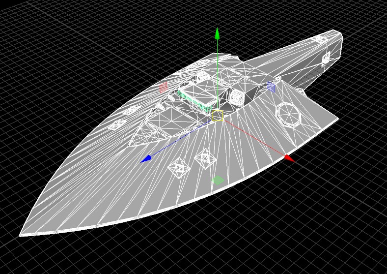
A few details aside, the collision model should look quite similar to your LOD2 mesh. Engines, thrusters as well as anything that does not have collisions can be removed (such as comm arrays and decorative poles). Reminder that is needs to be an air-tight shell. No holes, no overlapping geometry.
As mentioned in Stephmo’s guide, you have to cut this low poly mesh in as many sections needed to isolate convex shapes.
This convex rule is not absolute, but every deviation will cause some inaccuracy in the impact detection due to Unity’s “gift wrapping” of those meshes. Be aware that a collision part cannot be a perfect plane. Unity will replace those by a bounding box that does not respect the shape of that part.
TEXTURING
There are two major paths to texture a ship: 2d painting using a software such as Gimp, Affinity, Krita or Photoshop, or 3d painting using Substance, Mari or Ndo. I personally use the old-school 2d approach by force of habit, this means that some of this section’s content may not be applicable to everyone.
I believe that the game’s maps are made in a 3d texturing software using a mix of procedural textures and stencil brushes.
High Poly Model
Since I am using a 2d approach to textures, I require a highly detailed model to bake normal maps from:
The main purpose of this model is to add bevels that will catch the light and make the edges more visible, as well as kitbashing elements to break the uniform surfaces.
Baking
For baking the high poly model into a normal map for the visual mesh, I use a software called xNormal – [xnormal.net] . The outputs I’m interested for every hull section are the Normal maps, the Occlusion maps, and the Convexity maps.
I use the convexity map to find all the hard edges on the geometry and create paint scratches automatically with some 2d shenanigans.
Required Maps
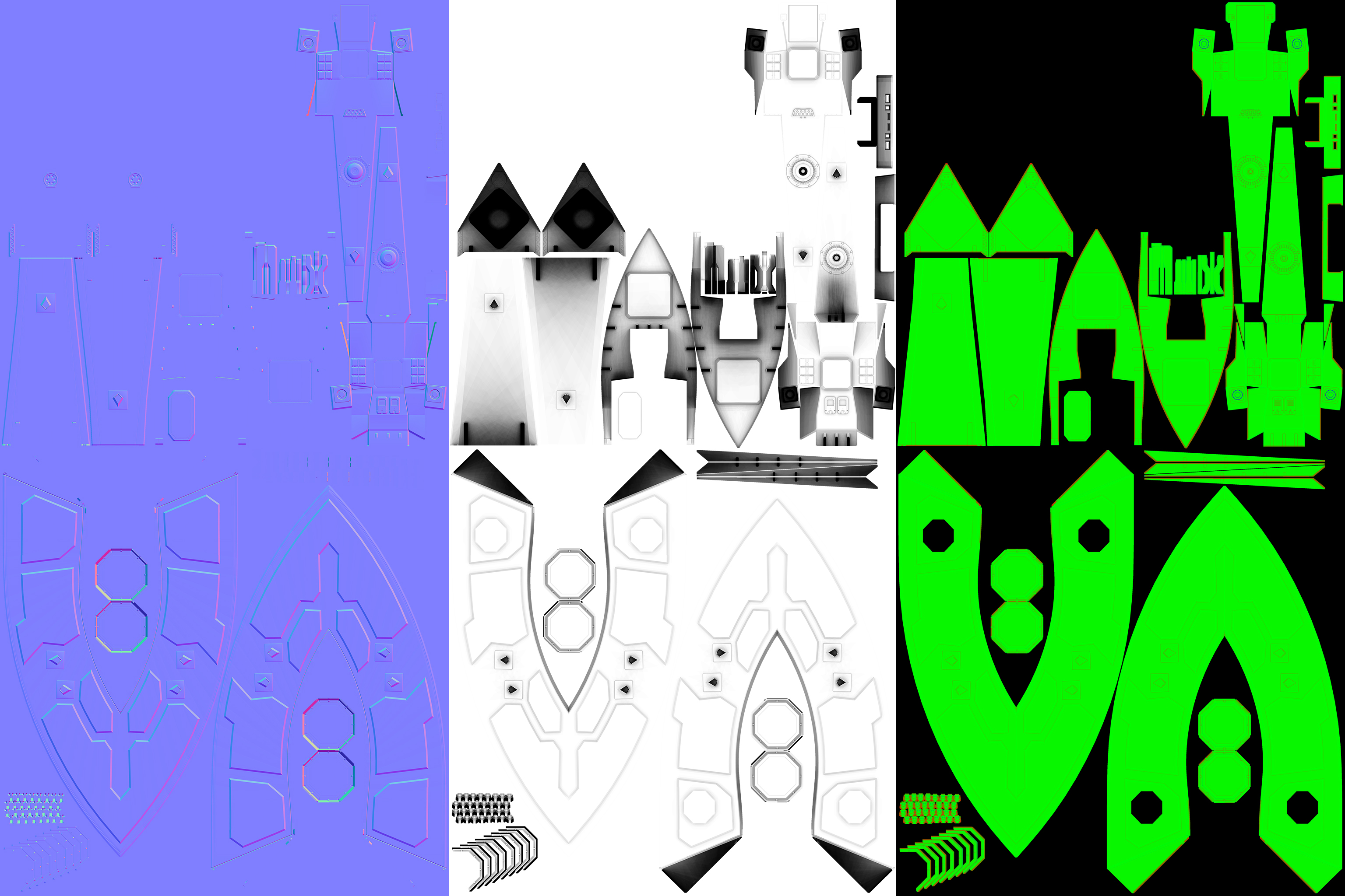
As mentioned before, the game uses 2048×2048 wide maps for everything except the engines sections that only use 1024×1024 maps.
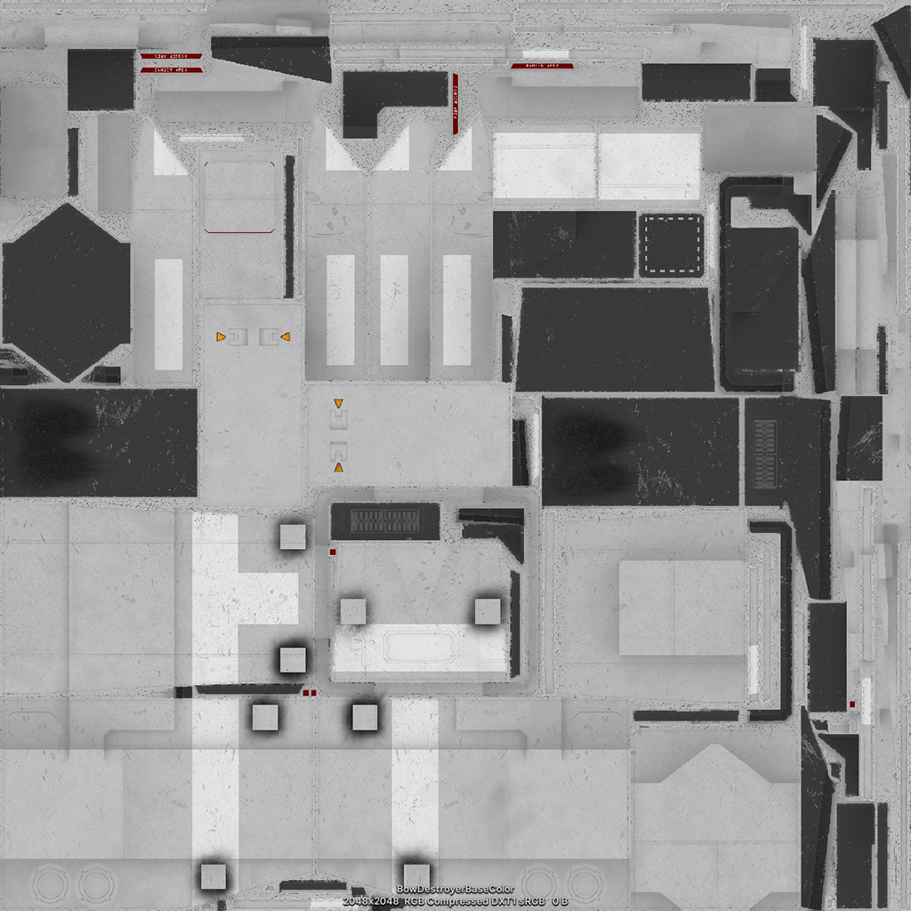
Diffuse or Base map
This is the base color of your hull. Make sure that areas that will receive custom paint colors are grey and not overly bright or dark.
Example with the Keystone’s nose base texture:
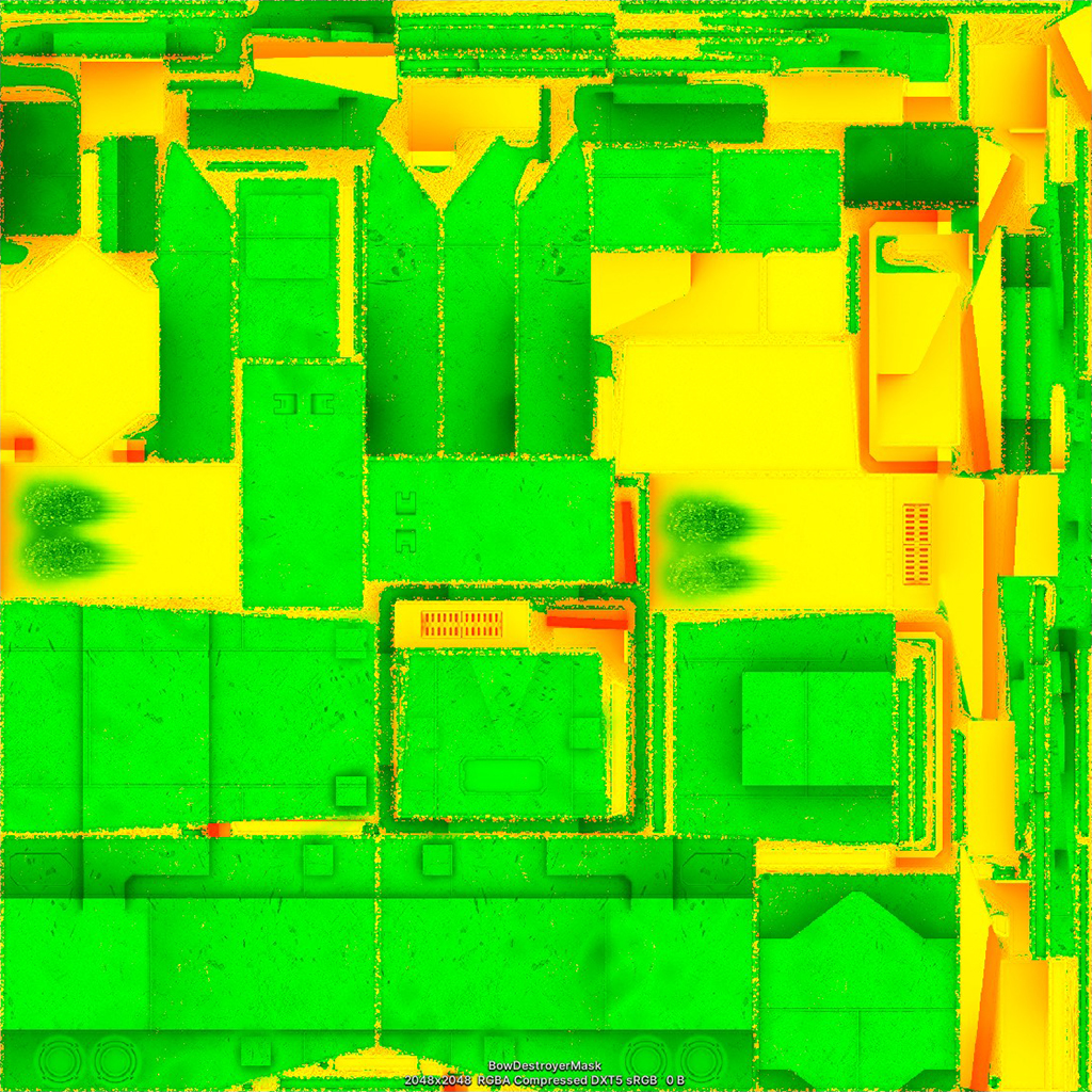
Mask map
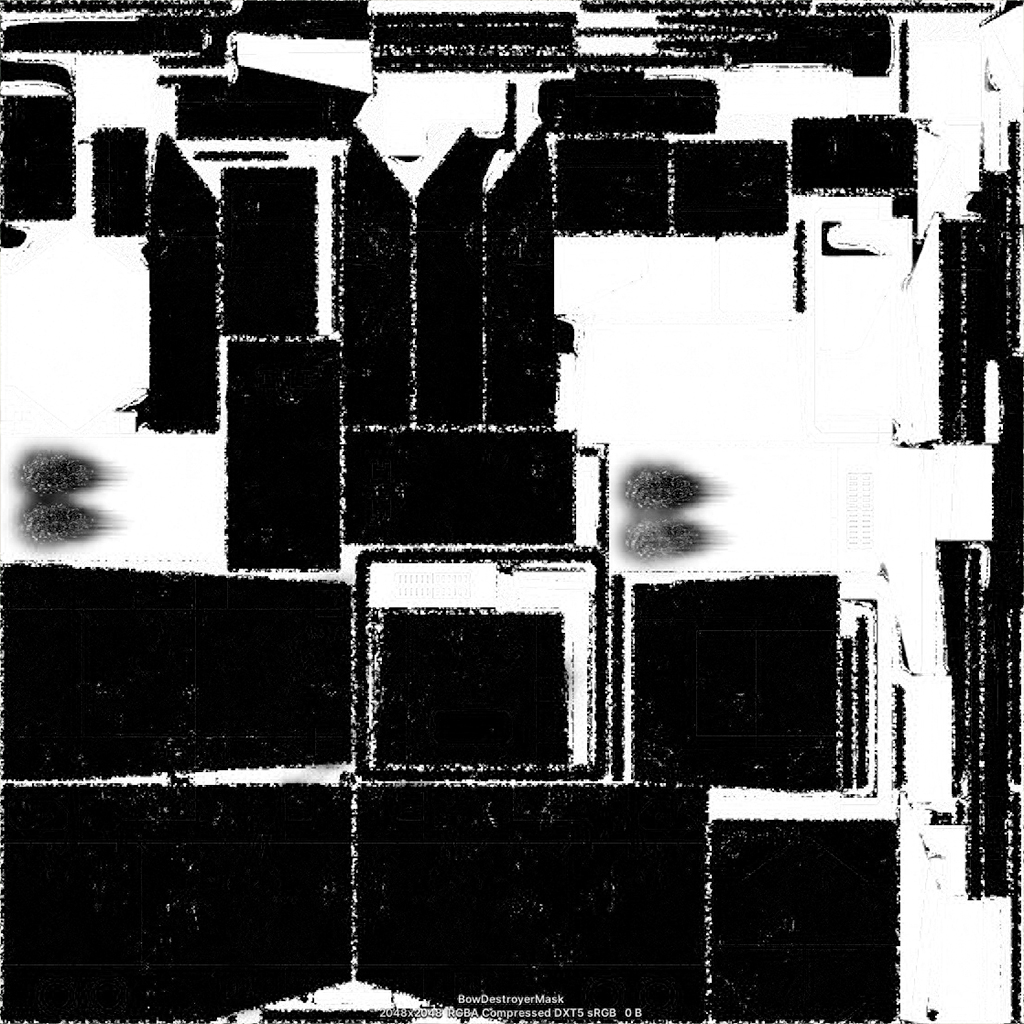
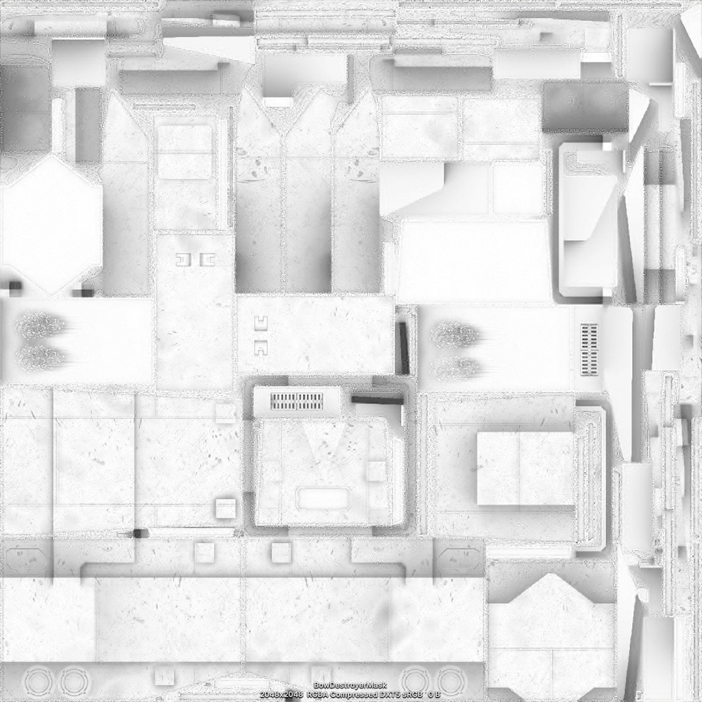
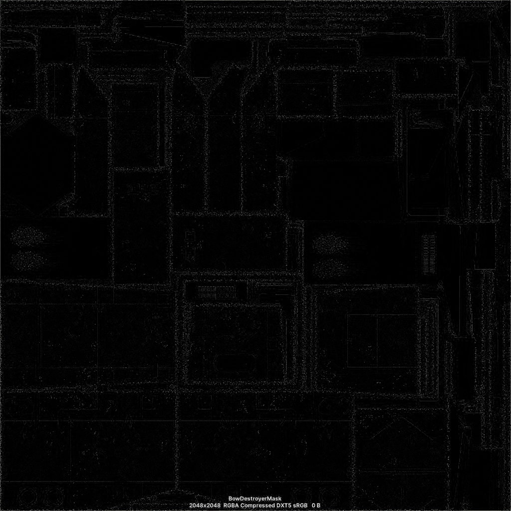
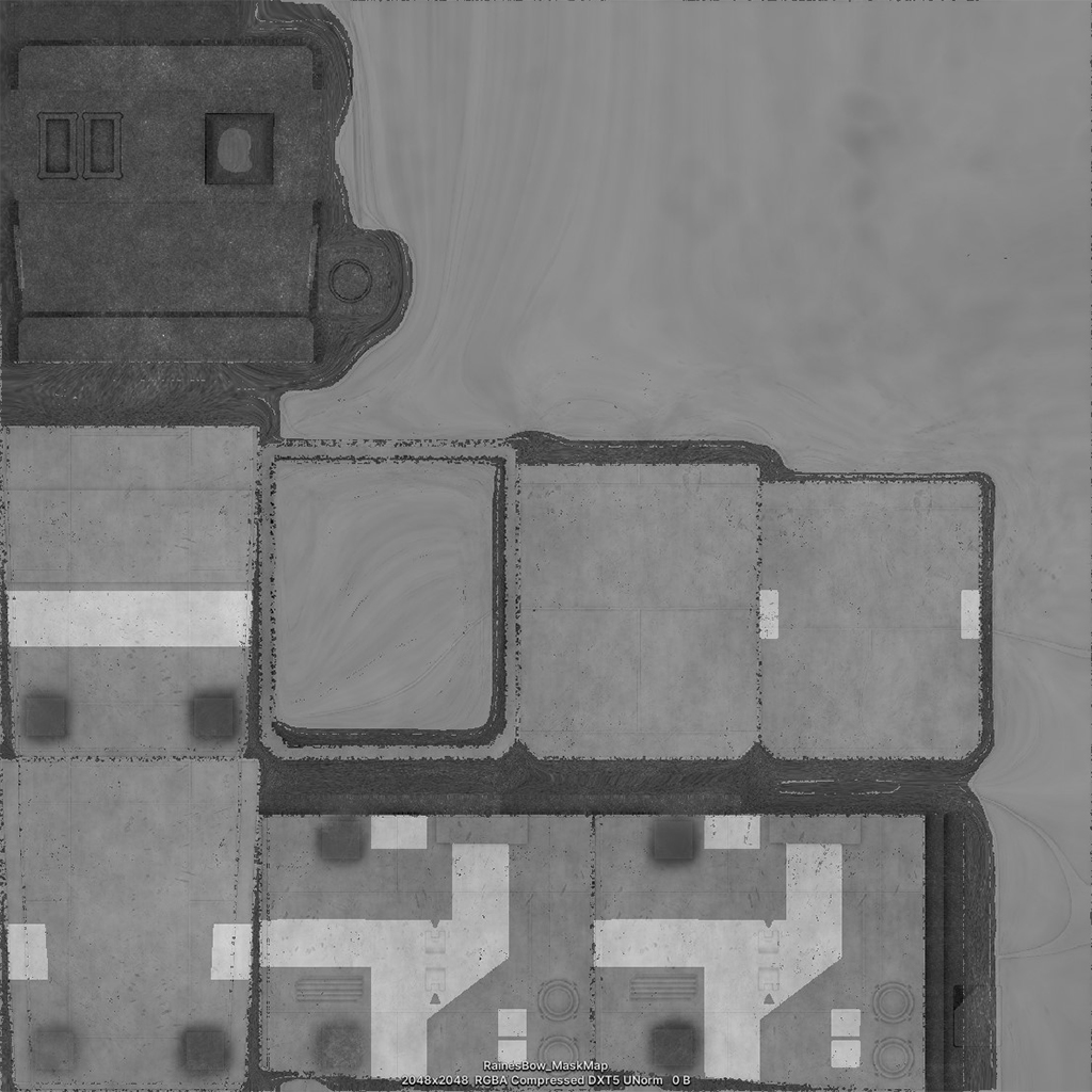
The Mask map is a composite texture that use each RGBA channel for a specific purpose:
R = Metallic (is the surface dull or shinny)
G = Occlusion map
B = Detail Mask (a mask for damage decals I believe, can be left black)
A = Smoothness (are specular highlights diffuse or sharp)
Example with the Keystone’s nose mask map:
Metallic:
Occlusion:
Detail Mask:
Smoothness:
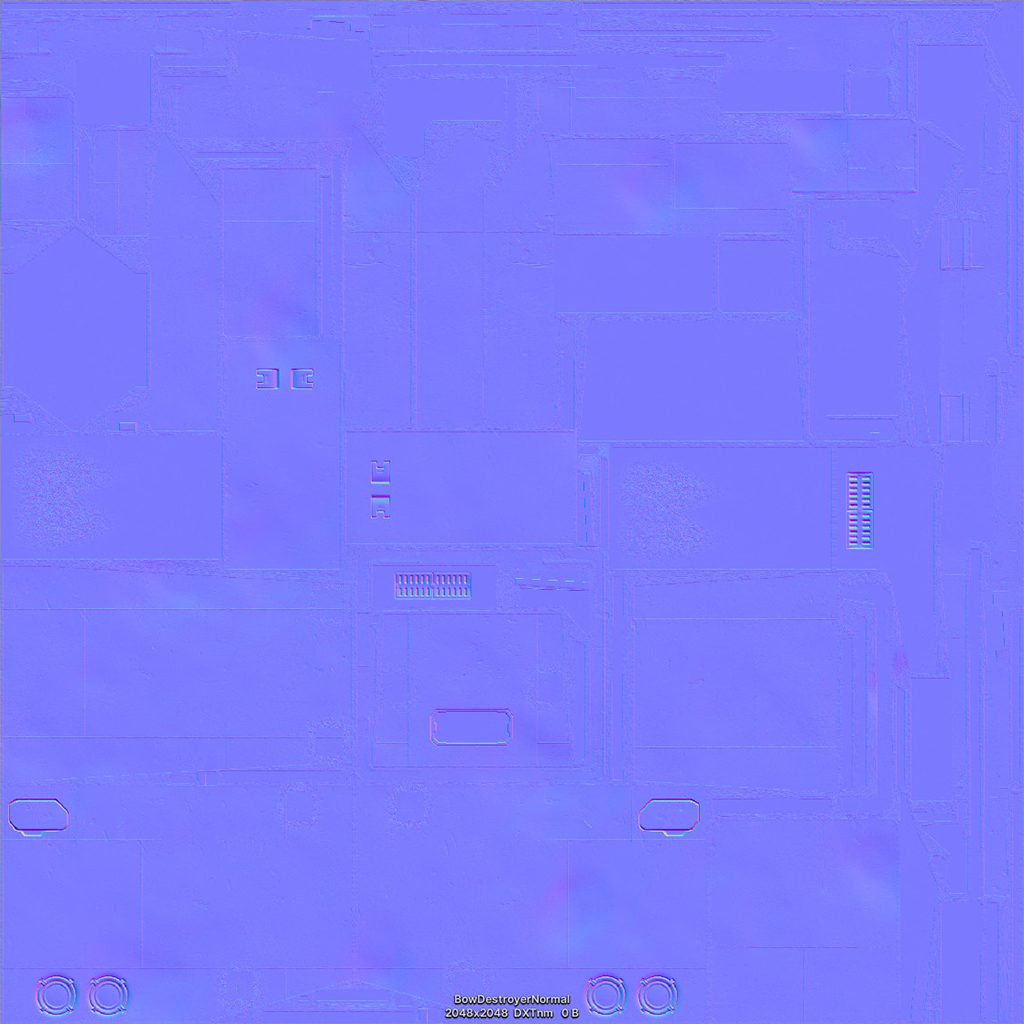
Normal map
Example with the Keystone’s nose normal map:
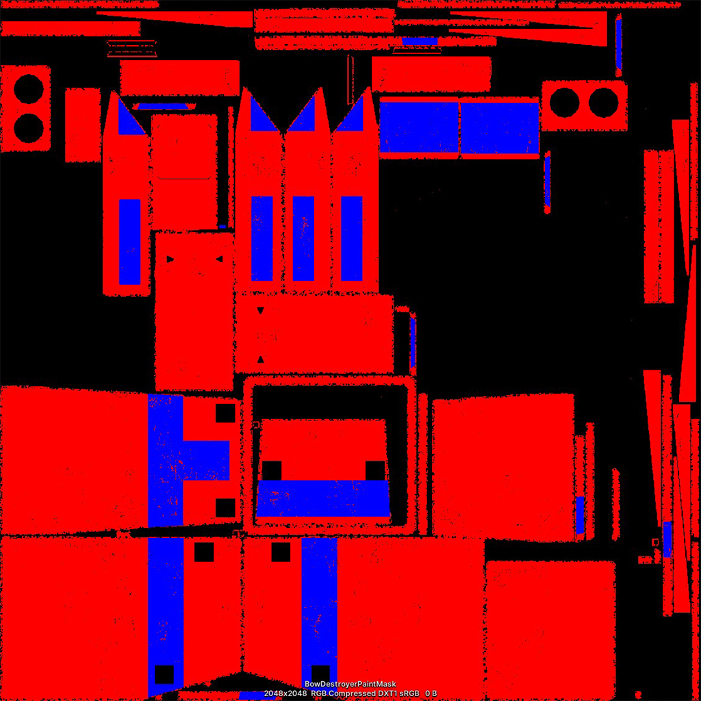
Paint mask
Another composite texture where
R = main color
G = unused
B = secondary color
Note that the secondary color will be applied over the paint color, meaning that if both masks overlap they will not mix.
Example with the Keystone’s nose paint mask map:
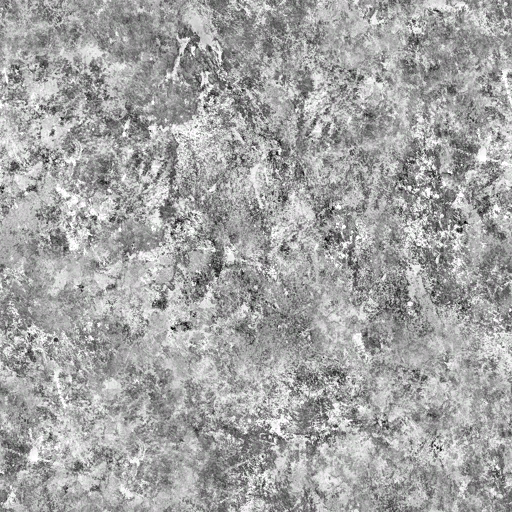
Armor Damage Base
This is a damage overlay for the burned hull by weapon impacts. This is the map available in the resources archive:
Armor Mask
The game’s hull shader also as an input for an “Armor Mask” map, this is the map added by the game to simulate damage and should be left empty.
Normal map from the base map
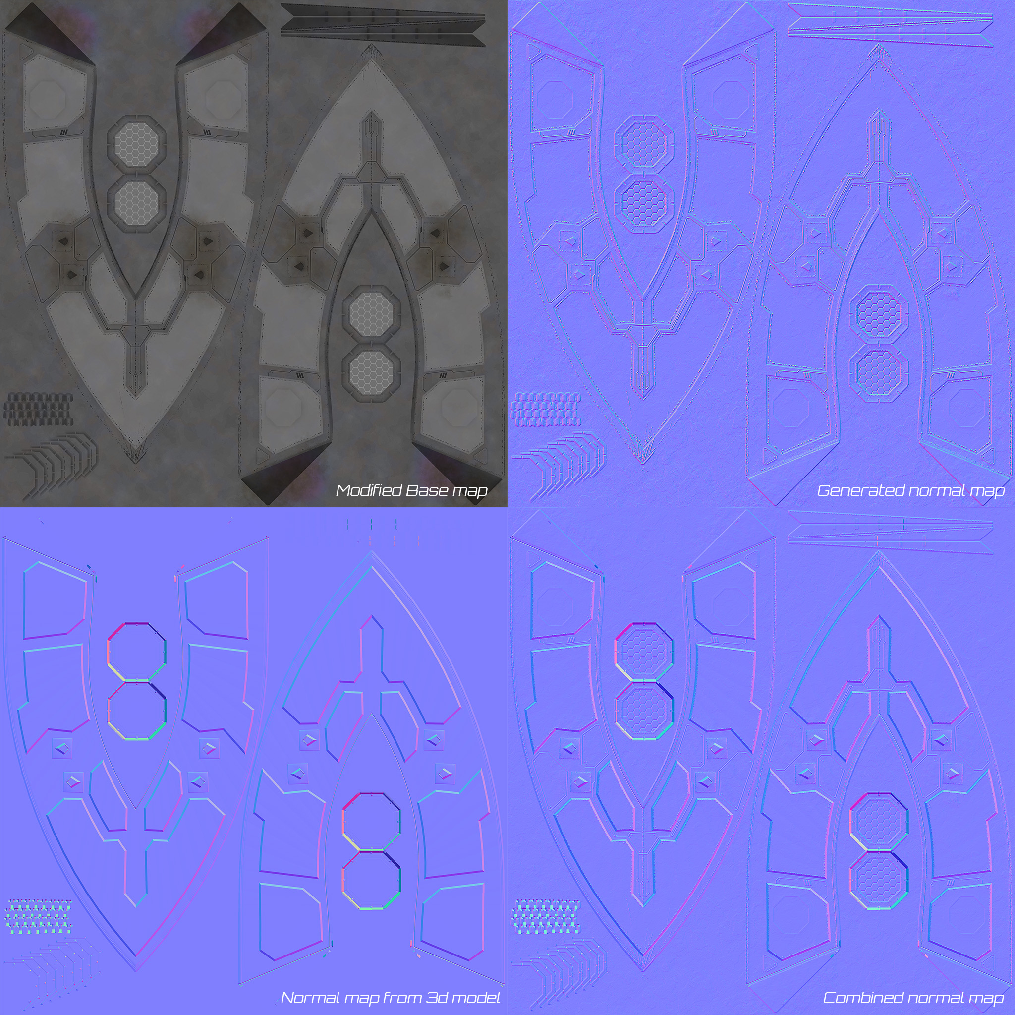
Since I create my textures in a 2d software, I need to generate normal maps from a variant of the base map so that the metal texture and the panel lines react to the light properly, then combine it with the normal map created form the 3d model. To that end I am using ModLab – [steampowered.com] .
The map used is slightly different from the base map: I hid all the painted stencils that are not supposed to have a volume, and inverted the scratches from white to black so that they are considered as crevices in the software and not highlighted bumps.
Result
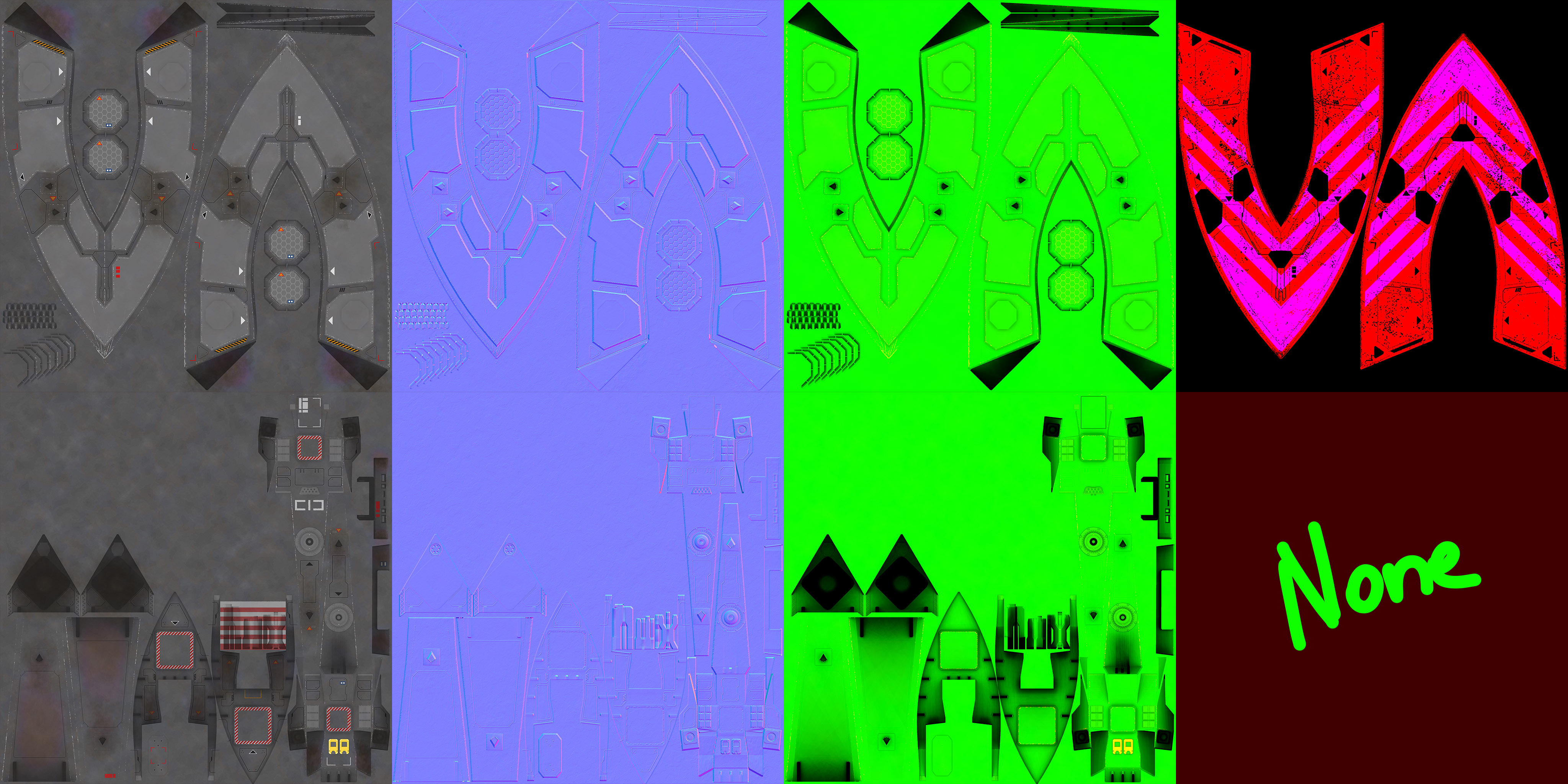
Here are the maps for this corvette:
TRANSFER TO UNITY
Exporting the visual model
There are three things to do before exporting the model:
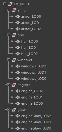
- Use this precise hierarchy and “_LODx” suffixes, that way Unity will automatically setup the levels of details upon importing the model.
- Ensure all the parts and groups have no values of transformation, that they all share the same pivot placed at the center of the scene and that this pivot is at the center of mass of the model.
- Triangulate everything!
Then you can export the model using a default FBX format.
Exporting the collision model
While no specific nomenclature is required for the collision model, I suggest renaming every section with a prefix indicating to which hull segment it is tied to. This will come in handy in Unity when you can have upward of 50 elements to assign to different collider scripts.
Make sure everything lines up with the displayed model, as well as ensuring all the pivots are placed to the center of mass like previously. A simple FBX export is then all that is left to do.
Exporting the texture maps
The textures need to be saved as DDS files, a very compressed format that is optimized for game use. There are many options and I would suggest reading about the features of this format if only because it is quite interesting (to me at least). However for the purpose of this guide, all you need to know is that the Base textures and the Paint Masks need to be exported with a DTX1 compression, while the Mask maps and the Normal maps require a DTX5 compression.
Unity’s modding project
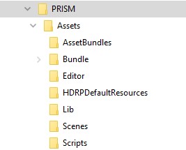
If you have not done it already, now is the time to setup your Unity project and mod folder following the official guide – [steamcommunity.com]” rel=”nofollow noopener”>official guide – [steamcommunity.com] . By the end of it, you should have a working folder hierarchy, a manifest.xml file waiting for content, and a build button in Unity’s action bar.
<?xml version="1.0"?>
<BundleManifest xmlns:xsd="http://www.w3.org/2001/XMLSchema" - []  xmlns:xsi="http://www.w3.org/2001/XMLSchema-instance"> - []
 <BasePath>Assets/Bundle</BasePath>
 <Namespace>yourPrefix</Namespace>
 <Hulls>
 </Hulls>
</BundleManifest>
And now, the fun part begins…
VISUAL MODEL SETUP
If you are discovering Unity, I would suggest at least learning about prefabs and how to manipulate them. The rest can be picked up fairly easily.
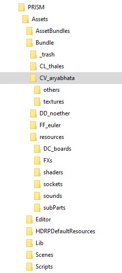
Here is how I organized my project:
Each ship has its own folder with the models you exported at the root, the maps in their “texture” folder, and a “other” folder to move stuff into as it is done.
Then there are a lot of prefabs and assets reused across the ships organized within the “resources” folder. You will need assets from the archive I shared in the introduction of this guide. Additionally some of the placeholder assets you will find within can save you weeks of time, literally.
Firstly, you want to make your ship folder part of your asset bundle. This will save you from assigning every individual component as you go along.
Note that you should keep your manifest.xml file at the root of your bundle folder.
Creating the Ship Prefab
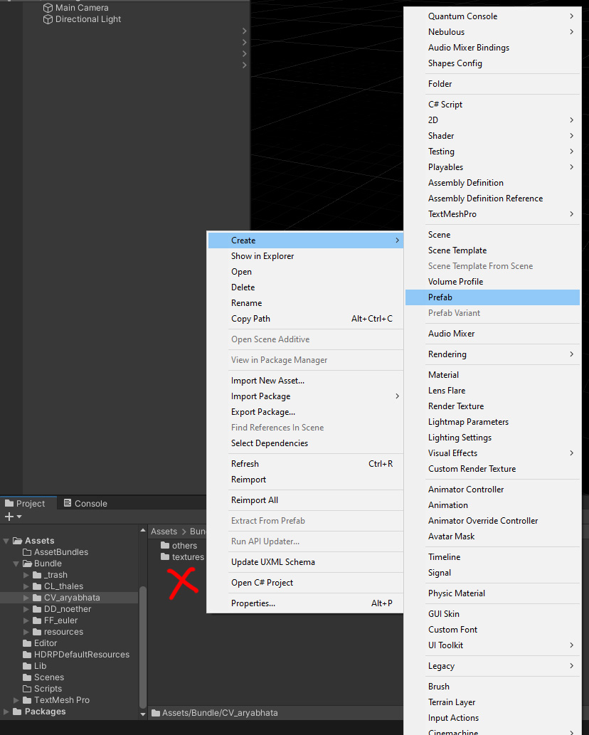
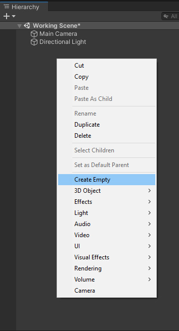
If it is your first time creating a prefab, here is the quick “How to”:
Option 1:
Right click in the Project window > Create > Prefab
Option 2:
Right click in the Scene Hierarchy window > Create > Empty game object:
Rename it after your ship:
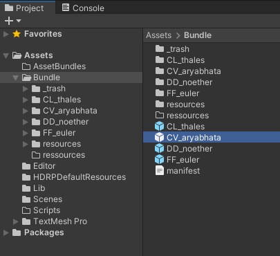
Drag and drop that object from the scene hierarchy to the bundle folder in your project window
Now that object is a “prefab” meaning that it can be instantiated, and all instances of it will inherit the prefab’s proprieties unless overridden. Those prefabs can be removed from the Scene as since they are their own assets now. If by mistake you edited an instance of a prefab in the scene instead of the prefab itself, you can apply the changes to the prefab using the Overrides drop menu from the top right.
You can now assign that prefab to your Asset Bundle like the ship folder before, as well as add it to your manifest file:
<?xml version="1.0"?>
<BundleManifest xmlns:xsd="http://www.w3.org/2001/XMLSchema" - []  xmlns:xsi="http://www.w3.org/2001/XMLSchema-instance"> - []
 <BasePath>Assets/Bundle</BasePath>
 <Namespace>prism</Namespace>
 <Hulls>
 <Entry Name="FF_euler" Address="FF_euler.prefab"/>
 <Entry Name="DD_noether" Address="DD_noether.prefab"/>
 <Entry Name="CL_thales" Address="CL_thales.prefab"/>
 <Entry Name="CV_aryabhata" Address="CV_aryabhata.prefab"/>
 </Hulls>
</BundleManifest>
(Note that the order of the ships in the fleet editor is driven by that list)
Do not forget to assign the manifest to your Asset Bundle too.
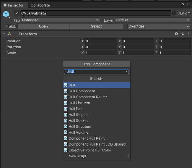
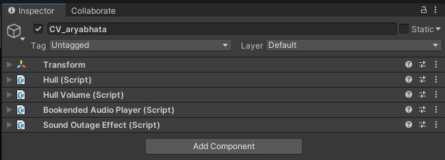
Double click on the prefab in the project window or on the “>” icon to the right of the name in the hierarchy window to edit the prefab itself rather than the instance in the scene.You can then add components to this ship prefab:
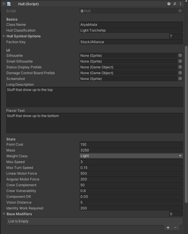
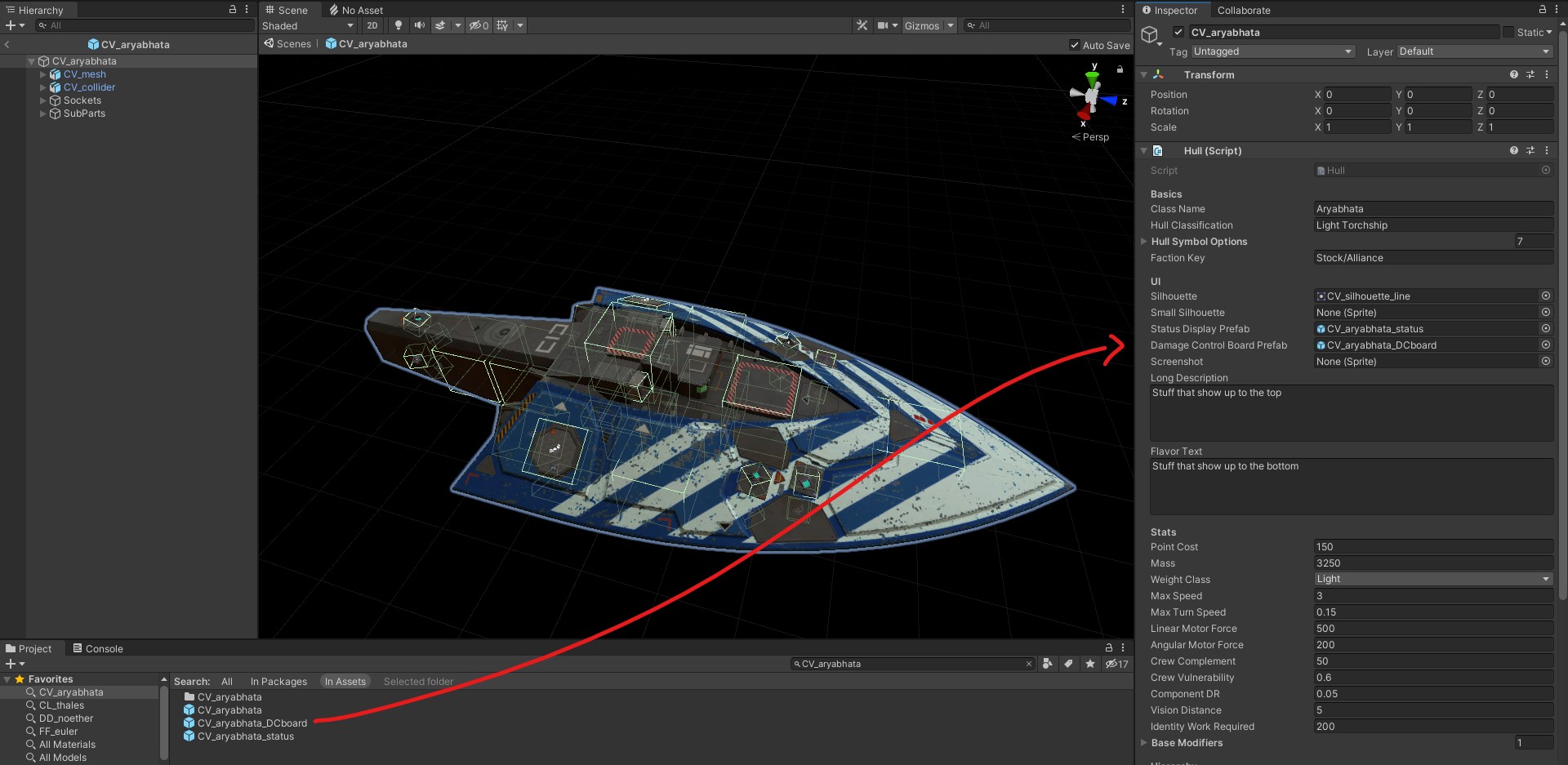
You can already fill in a few variables for the hull script, but most of them will requires future elements:
(Note that the Max Speed stat needs to be divided by 10 because the game is at a 1/10th scale)
Importing the model
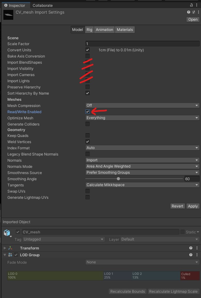
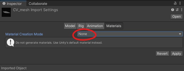
If you have not already, place the visual mesh file into your ship folder. The LOD groups should automatically get created but there are a few boxes to tick and untick to finish the import:
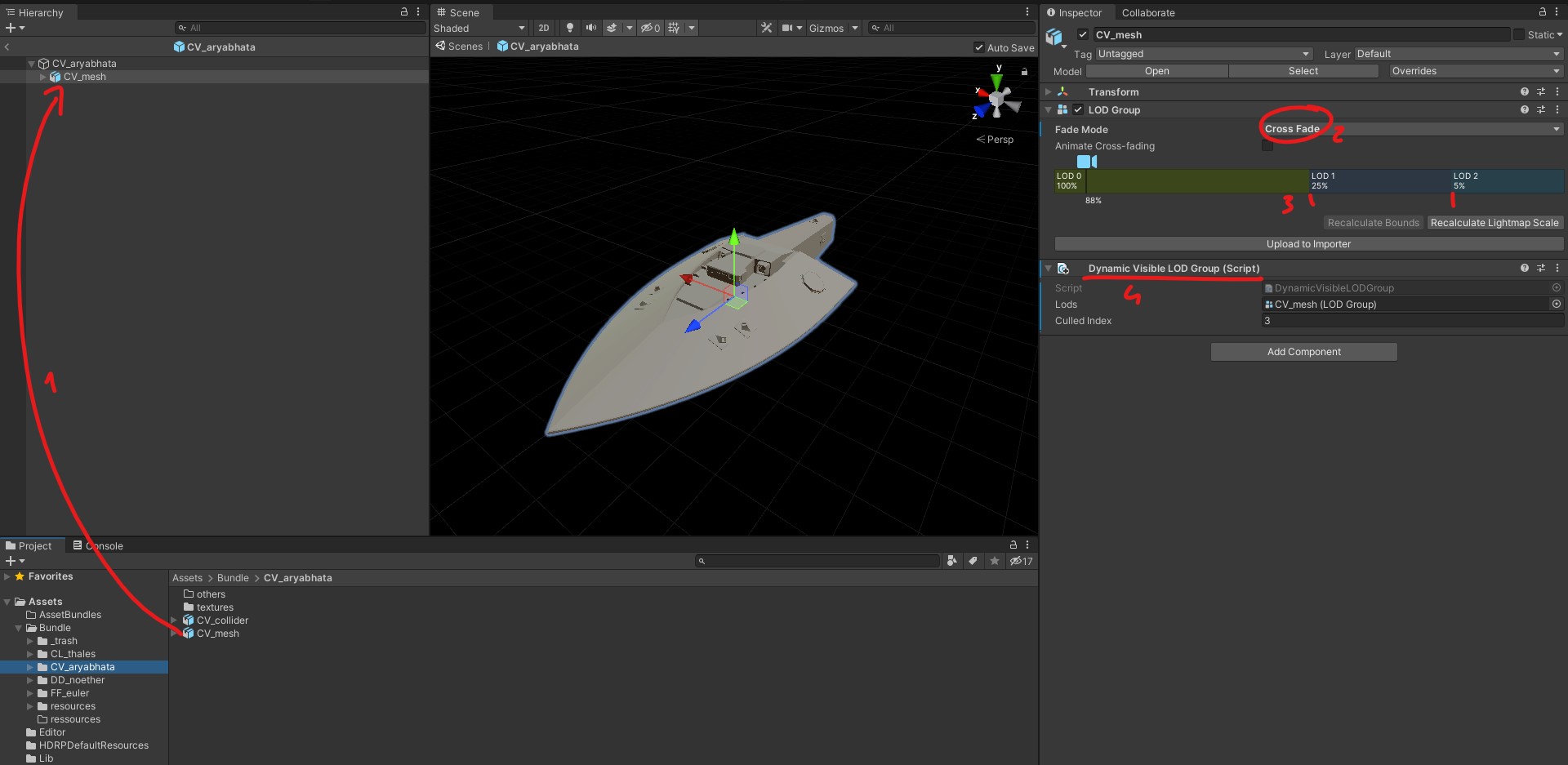
[1] Place your model into your ship prefab, make sure all transforms are zeroed.
[2] Set the LOD change to crossfade for a smooth transition,
[3] You can tweak the thresholds for each level (I personally use 25%, 5% and no culling),
[4] Add the Dynamic Visible LOD group script.
MATERIALS
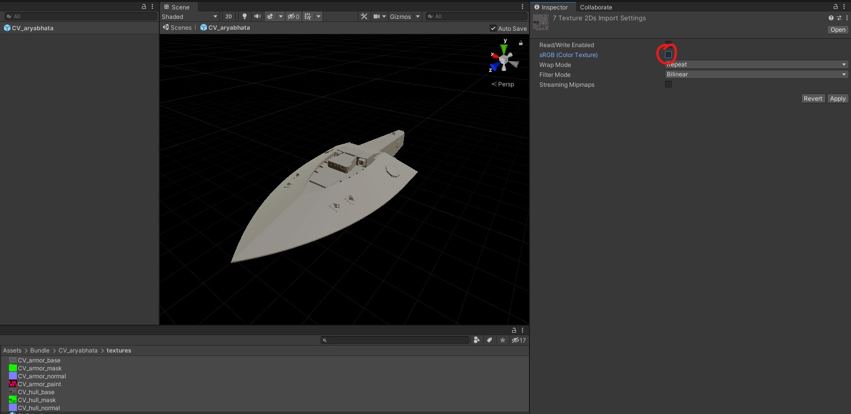
If you have not already, place your texture files inside the texture folder in your hierarchy. By default they will be imported in a sRGB color space because the project uses the “high definition pipeline”. That must be turned off on all textures except the base maps to avoid issues.
You will need one material per hull section, so in my case engines, hull and armor. The windows and the engines glow materials that can be shared across ships.
Right click in the project window in the texture folder > Create > Material > give it a name.
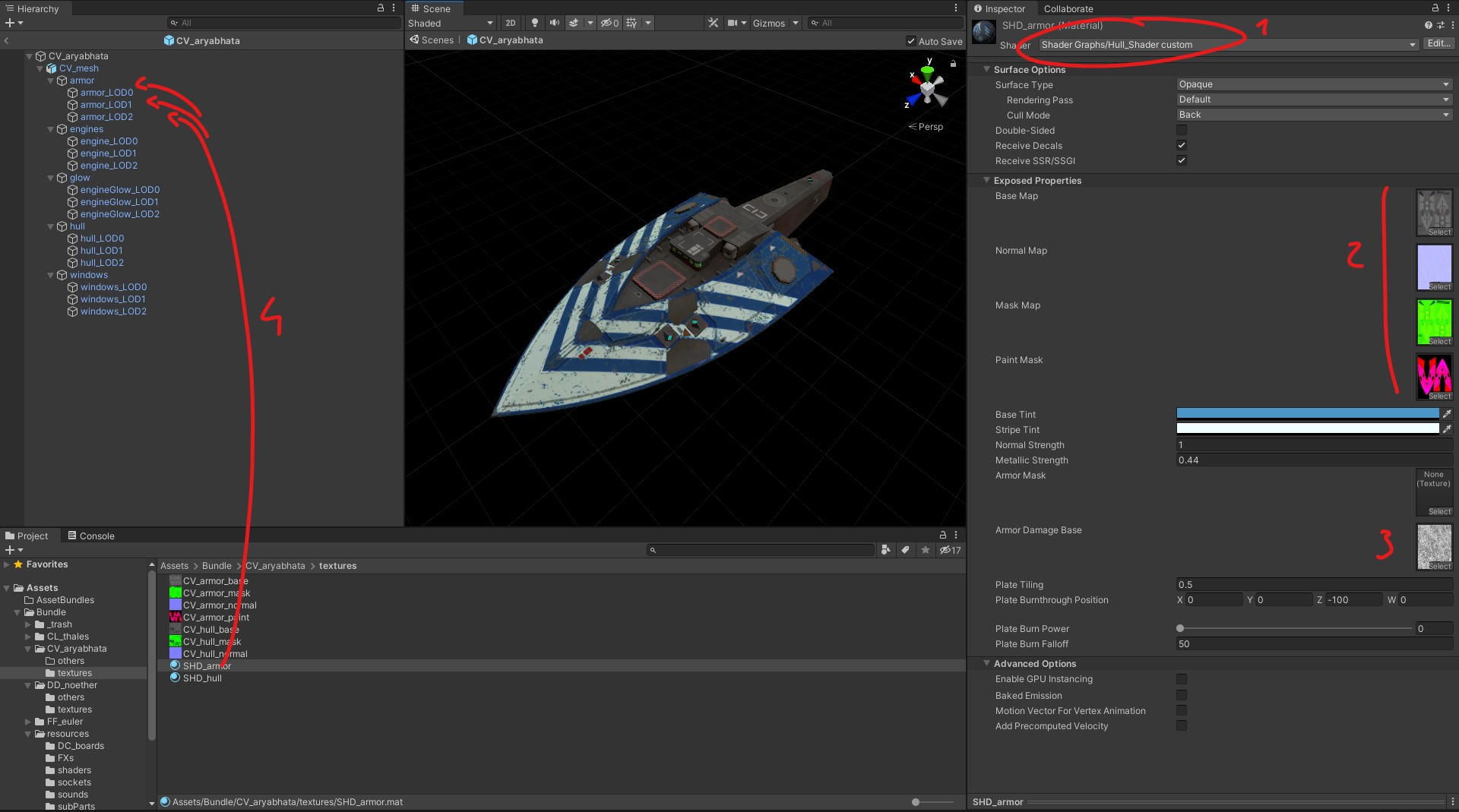
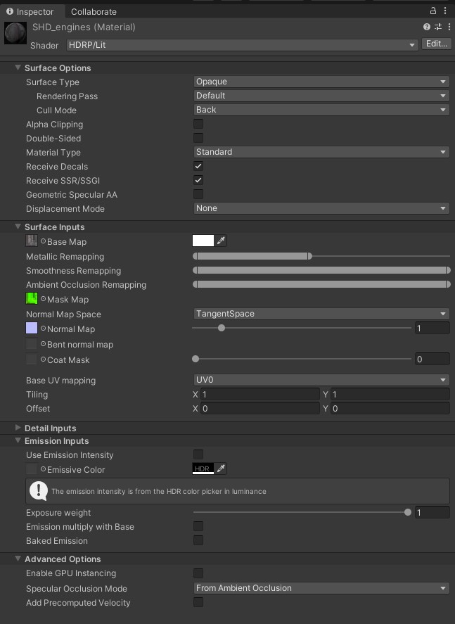
[1] The hull materials need to use Shader Graphs > Hull_Shader vanilla or Hull_Shader custom.
[2] Drag and drop the relevant maps into their respective slots or use the “Select” button.
[3] Plug the “damage” texture from the resources/shaders folder to the Armor Damage Base.
[4] Assign this material to all three relevant LODs meshes.
The differences between the custom hull shader from its vanilla counterpart are a slightly different way to handle black or white paint colors, as well as a better blending between base and stripe colors around fuzzy edges.
Beware: If a section of your ship does not have a paint mask because it is just bare metal, you still need to slot a black texture to the paint mask.
For each hull section you will need to add a Hull Segment script and assign the same material to it. This is the script that links the damage model to the textures:
Note that you can use the lock to the top right to keep a selected object in the inspector while you are browsing the project window, to drag and drop the material in the proper slot for example.
The engine segment material is a default HDRP_lit material using the same type of textures.
Assign the SHD_glow material from the resources/shaders folder to the engine glow meshes.
You can then add the Emission Outage Effect and LOD Group Shared Material scripts to the engine glow mesh group, assign color ramps to the former and the material to the later.
Assign the SHD_window material from the resources/shaders folder to the window meshes.
You can then add the Lights Outage Effect and LOD Group Shared Material scripts to the engine glow mesh group, assign color values to the former and the material to the later.
Back to the ship prefab, you can find the “Effects” section of the Hull script and now assign the engine glow and the window scripts to the relevant slots:
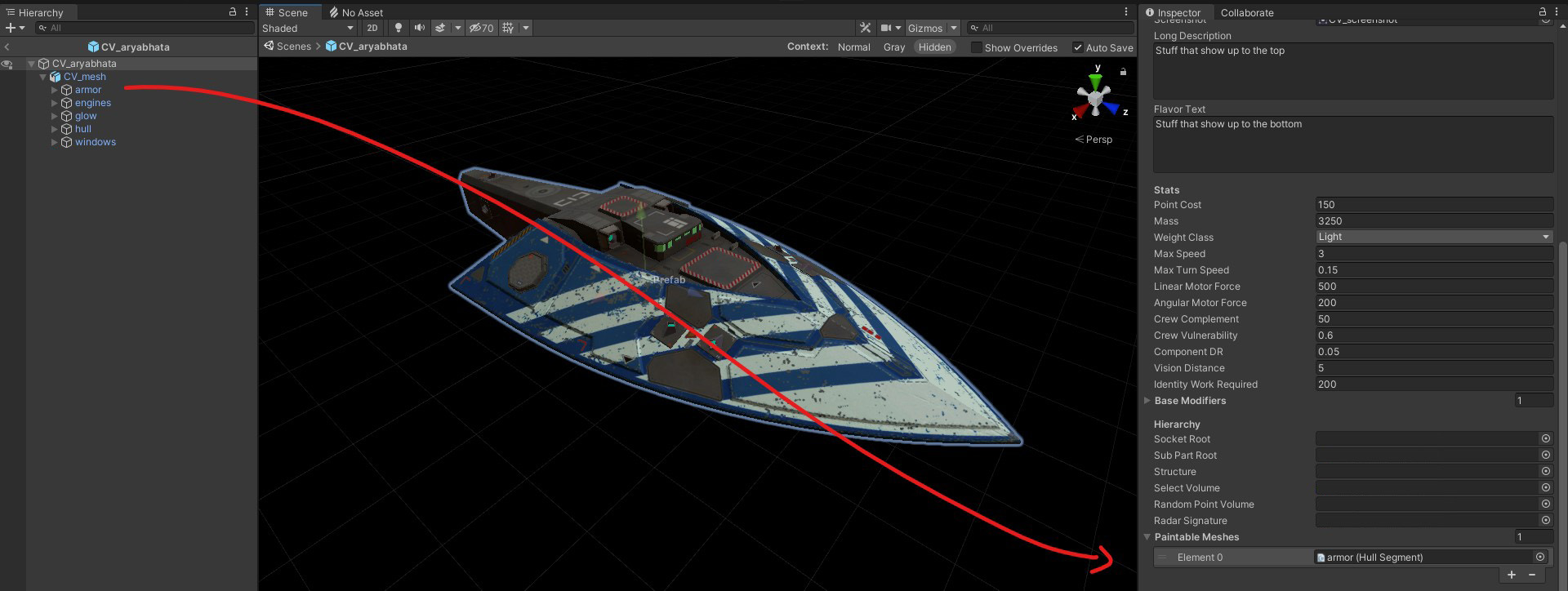
You can also slot the relevant hull segment into the Paintable Meshes list:
COLLISION MODEL
If you have not already, place the collision mesh file into your ship folder. You can then tick and untick the same boxes as you did with the visual mesh.
Setting up the Collision Model
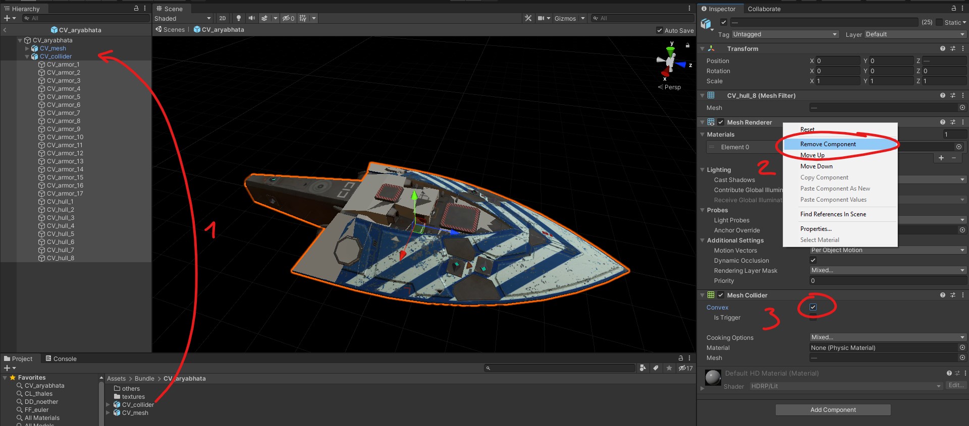
[1] Drag and drop the collision mesh into your ship prefab. Make sure the transforms are all 0,
[2] Select all the parts inside and remove the Mesh Renderer component so that they are not visible ingame,
[3] Add the Mesh Collider component and tick on the Convex box
(If you unpacked the game assets you will notice this method is different from Vanilla ships, but it is easier to setup)
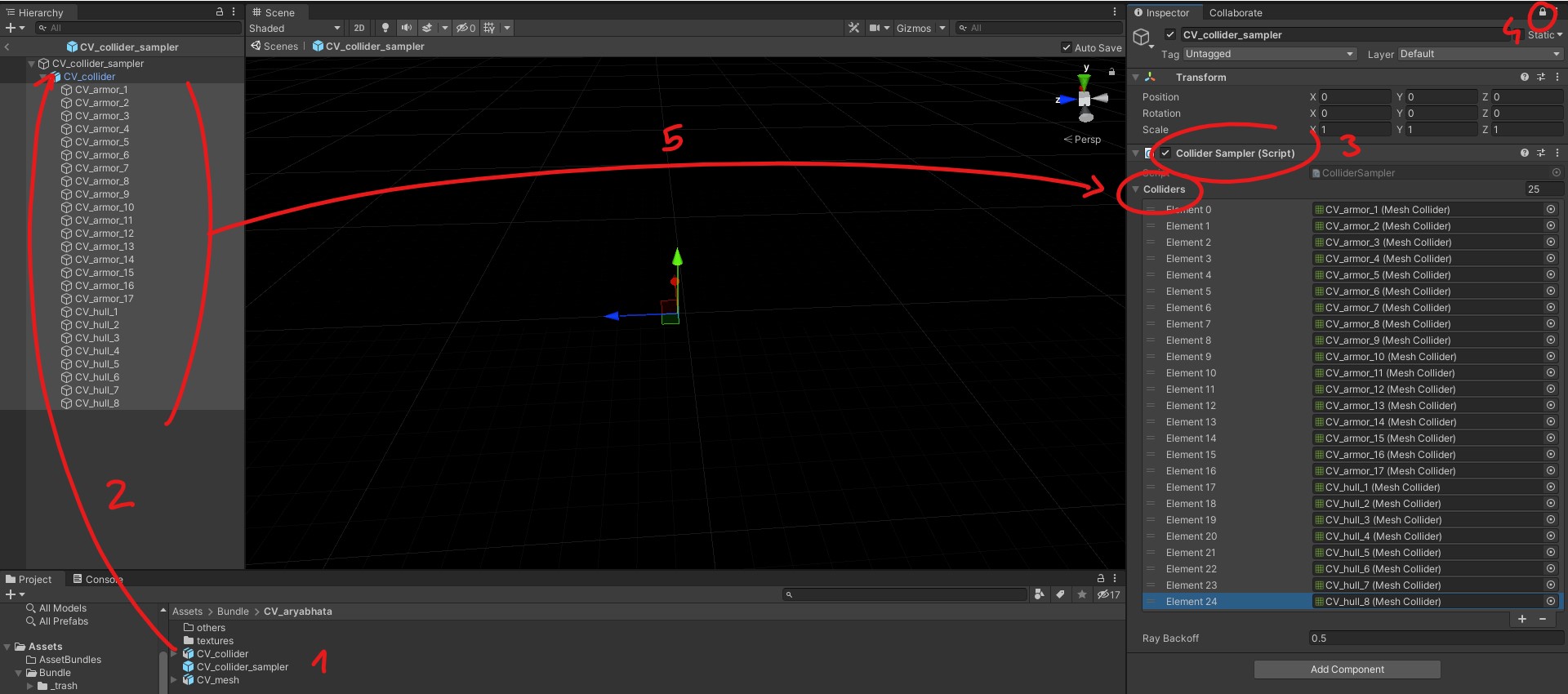
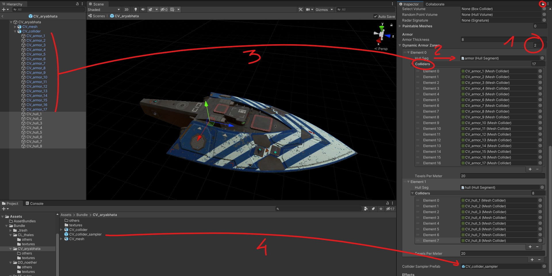
[1] Right click in the project folder and create an empty prefab. Rename it “Collider Sampler”.
[2] Place the collider mesh inside, just like before add the Mesh Collider component to all the parts.
[3] Add the Collider Sampler script to the Collider Sampler prefab,
[4] Lock to the inspector window to make your life easier,
[5] Select all the parts from the collider mesh, drag and drop them on the empty Collider drop menu to add them all at once.
Now go back to your ship prefab and find the Armor section of the Hull script.
[1] Start by setting the number of armor zones, that is the number of hull segments for your ship.
[2] For each element, select a hull segment from the list opened with the dot icon,
[3] For each element, drag and drop the relevant collider parts to the Colliders drop list,
[4] Add the Collider Sampler you just created to its slot in the Hull script.
SOCKETS AND HULL PARTS
Now this is the fun part!
Adding Sockets
Sockets are game objects that will receive weapons, modules and compartments. All these objects require unique identifying Keys, which leads to two methods for creating them:
You can either create a new object for each one of those sockets: adding the relevant scripts will generate a unique Key that can then be copy-pasted when needed. Since you will need to set the size and values in the scripts every time it is a laborious but error proof method.
You can also duplicate your components as needed, and even prepare prefabs in advance for each object type, but you will then have to edit their Key each time, and be very careful to avoid collisions. It is a faster but otherwise error-prone method.
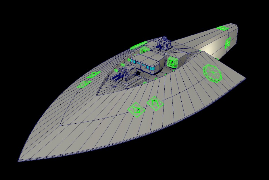
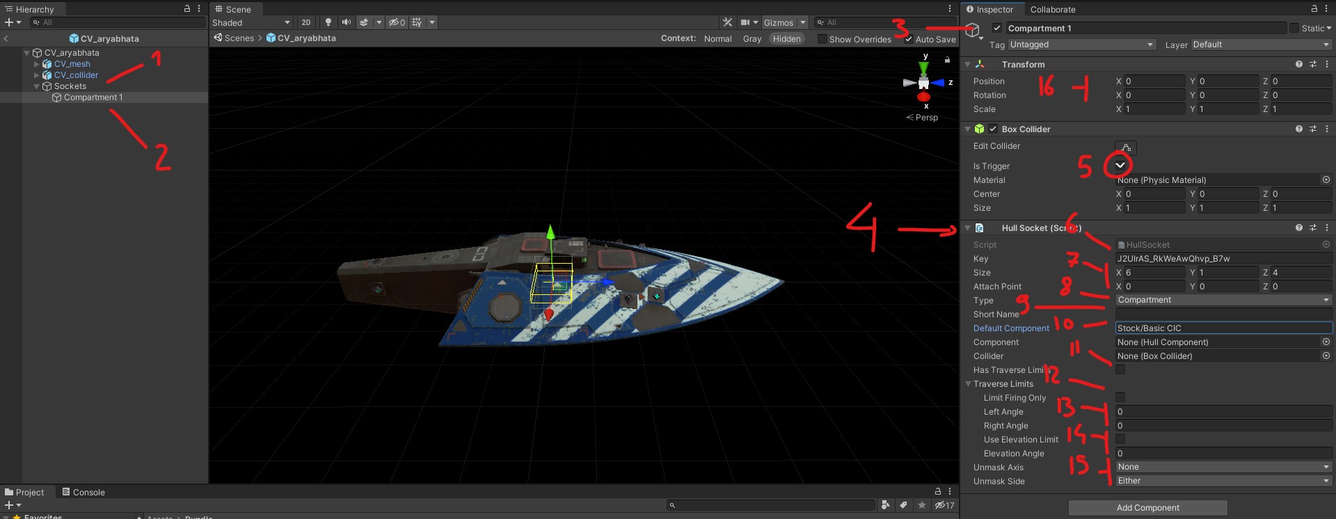
[1] In your ship prefab, create an empty game object that you will rename “Sockets”. Make sure its transforms are zeroed otherwise placing sockets will be weird.
[2] Inside the Sockets empty group create another game object.
[3] Name the object after the socket you want to create. This name will be visible in the Ship Editor so it should be both explicit and short.
[4] Add the Hull Socket script to this object, this will generate a unique Key for the Socket and create a Box Collider.
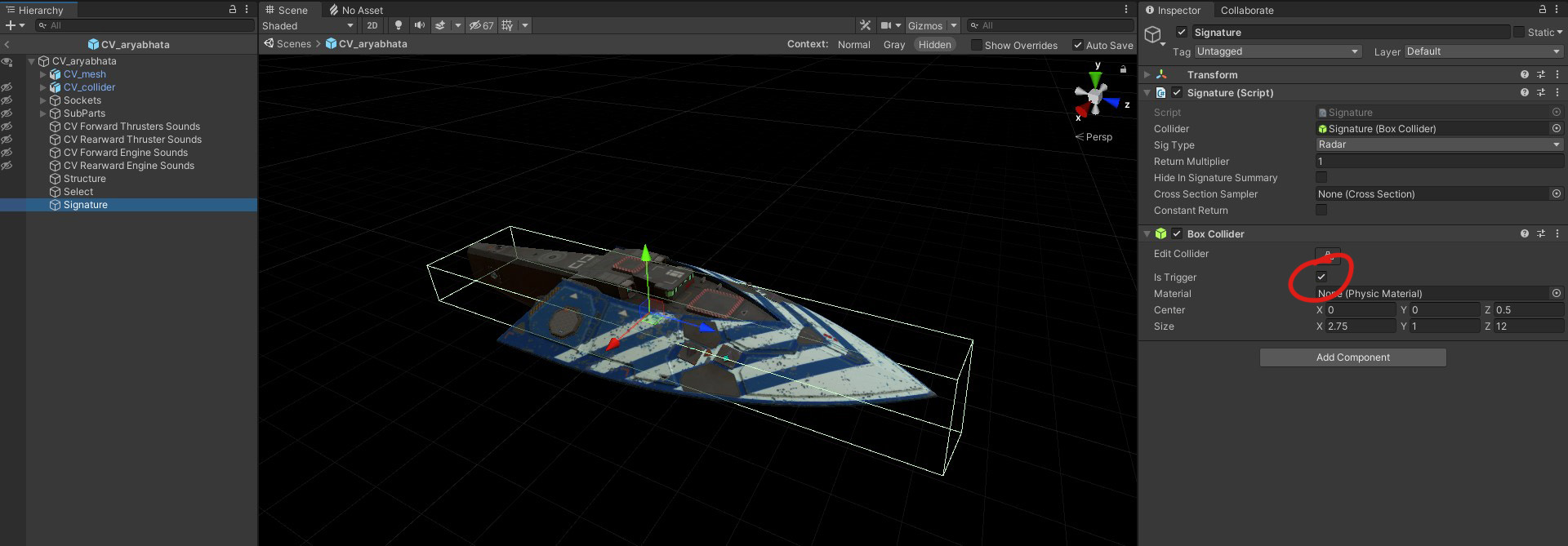
[5] The Box Collider needs to be a Trigger.
[6] This is the unique Key of the socket, if you want to turn it into a prefab, that entry will have to be modified for every instance of it. This Key will be referenced in the DC Board to link the UI to the game object status.
[7] Set the size of the object. The attach point offset is used for weapon sockets: those need to be inside the hull while the attach point is on the surface, exactly at the top of the volume (for example a 3x4x3 weapon mount has a 0x4x0 attach point).
[8] Set whether this socket is a Compartment, a Module or a Surface Mount
[9] In vanilla, surface mounts have a “MT” value there.
[10] Default component present when spawning an otherwise empty hull in the editor. In vanilla it is used for [Stock/Basic CIC], [Stock/FM200 Drive], [Stock/FR4800 Reactor], [Stock/RS35 ‘Frontline’ Radar], and [Stock/♥♥♥♥00 Micro Reactor].
Following are a few weapon mount-specific options:
[11] Enable traverse limits if the slot does not have a full unobstructed 360 degrees coverage. Note that all vanilla weapons have a 5 degrees maximum depression.
[12] Whether the weapon can still rotate outside of the traverse limits (such as having an obstructed field of fire but nothing close enough to physically block the barrel)
[13] The width of the available traverse left and right of the rest gun position.
[14] Whether there is an elevation from which the weapon can still fire while outside of its traverse limit.
[15] What should the ship present to a target to allow the weapon to fire. Side axis or top axis, then positive, negative or either halve.
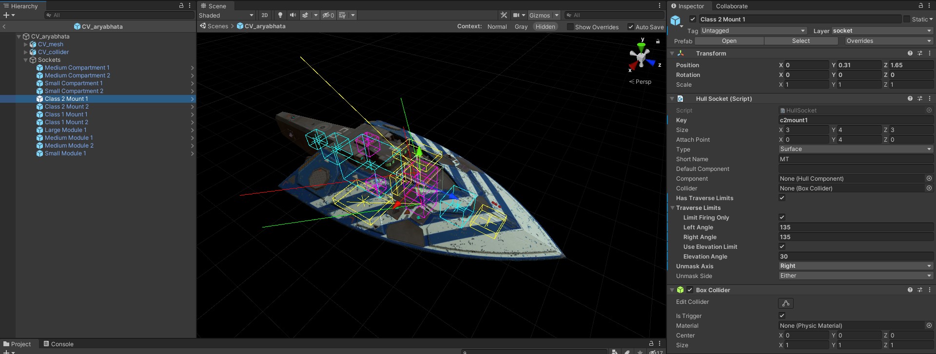
[16] Once the socket is setup, you can place it wherever it is needed. Compartments and Modules should be entirely inside the hull, while weapon mount should be placed right on the surface.Those objects can be scaled if a socket larger than the available room is needed for balance purpose. They will still be able to mount components available to the stated size, while not pocking outside the hull. Although for surface mounts it will also scale the visible weapon/device.
The most common socket sizes in Vanilla are:
Surface Mount = [2,2,2] [3,4,3] [3,4,5] [6,4,6] [8,7,8] [4,12,4]
Compartment = [3,1,3] [4,1,6] [6,1,6] [6,1,8]
Module = [2,2,2] [3,3,3] [6,6,6] [10,8,10]
drive module sizes are free-form as long as they are larger than [5,5,5]
Once you have placed all the sockets for your ship, you need to set the Sockets group as part of the layer 11, create it if needed. That will ensure all the sockets inside are also part of the layer 11 and can be damaged by rounds that penetrate the hull.
Placing SubParts
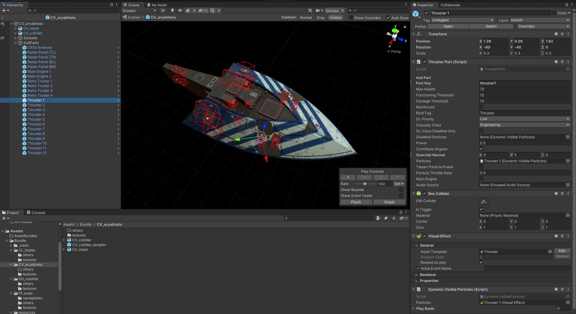
SubParts are damageable game objects part of the hull itself such as engine nozzles, radar panels and antenna arrays. Similarly to sockets they need unique identifying Keys so the same methods and caution apply here.
Like previously, create an empty game object in your ship prefab named “SubParts”, inside which you will place various objects. There are 3 types of Sub-Parts with different script components to add:
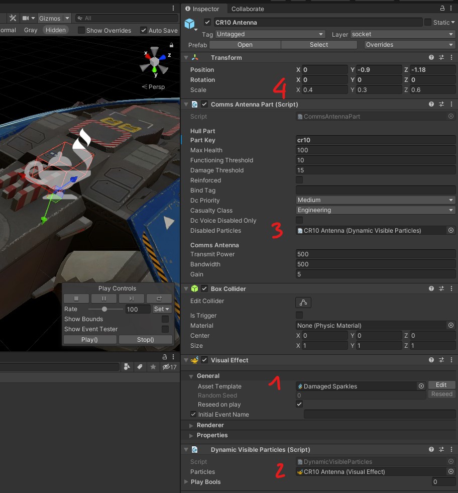
Antennas
[1] This is the damaged sparkles effect visible when it is disabled. There is a section dedicated to FXs in the appendixes of this guide, for now you can use the effect I provided in the resources folder.
[2] The Visual Effect component can be referenced in the Dynamic Visible Particles script.
[3] That can then be referenced in the Disabled Particles input of the Comms Antenna Part script
[4] Unlike Sockets, SubParts are just a collision object, they do not have a default “size” and are simply scaled as needed. Note that you can also use Sphere or Capsule colliders for all SubParts depending on their shape.
Radar Panels
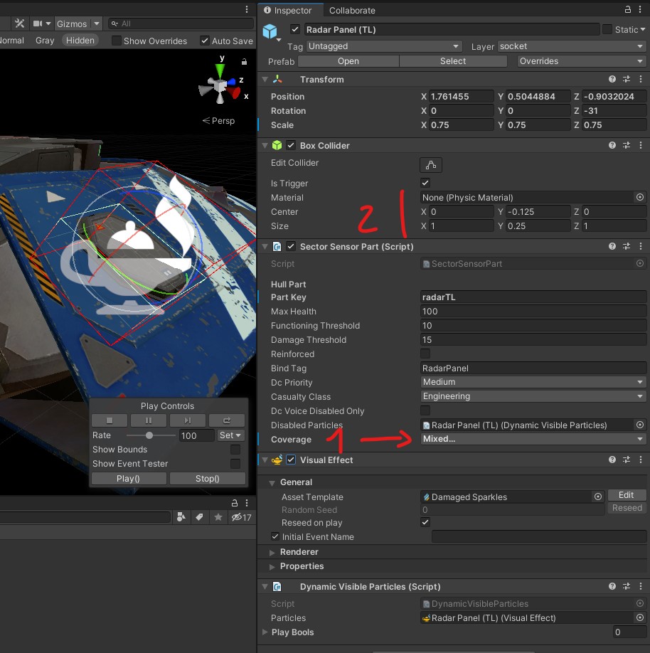
[1] By default a radar panel covers everything. To be consistent with Vanilla ship they should only cover a portion of the sky defined as any combination of +/-X, +/-Y, +/-Z relative to the ship’s orientation.
[2] There I modified the collider so that I get the desired box shape when snapping my prefab to the model of the panel. This is only for convenience and not something required.
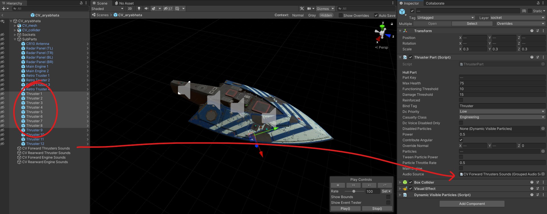
Engines/Thrusters
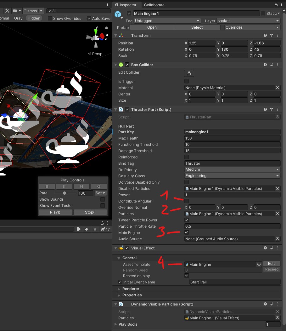
[1] This sets if this engine can be used to rotate the ship in addition to move it.
[2] When using thrusters that are not exactly aligned in one axis, it is a good idea to enable an override so that they are not fired for change they contribute little to. For example if a top thruster is inclined a couple degrees to the front, you might not want it to be used to slow down the ship.
[3] Self explanatory but important to properly set. Note that Main Engines usually have 150 HP while Maneuvering Thrusters have 75.
[4] Please note that Main Engines, Bow Engines and Attitude Thrusters have different visual effects. If you have a doubt on the orientation of the engine, you can use the “Play()” button to enable the particle effect.
Like previously, you need to set the SubParts object to the Layer 11 and apply that to everything inside.
It is a good idea to do a thorough checkup once you are finished fiddling with sockets and subparts. Make sure all the names and Key are properly set and that everything is on the layer 11, that the turrets have the proper unmasking values when needed… It is very easy to miss a thruster normal override, or mess up one Key.
Finally going back to your ship prefab, you can now assign the Socket and SubParts objects to the Hull script:
FX GRAPHS
To Do
STATUS BOARD
You may have heard rumors about this part being absolutely dreadful to go through. Let me reassure you that it is only true for the first one you will make. Then it is just busywork that requires minutia but is not otherwise difficult.
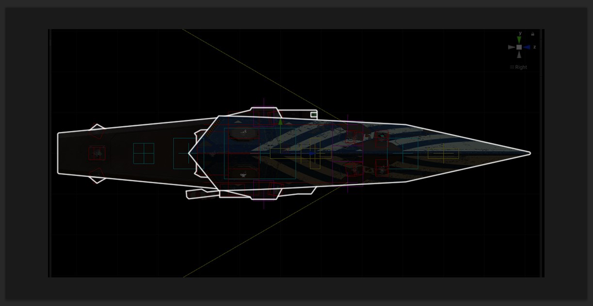
The first thing you will need for the Status Board is a transparent ship outline .PNG sprite 1024x512px wide as well as an orthogonal screenshot of the ship with its sockets and subparts gizmos that lines up with it.
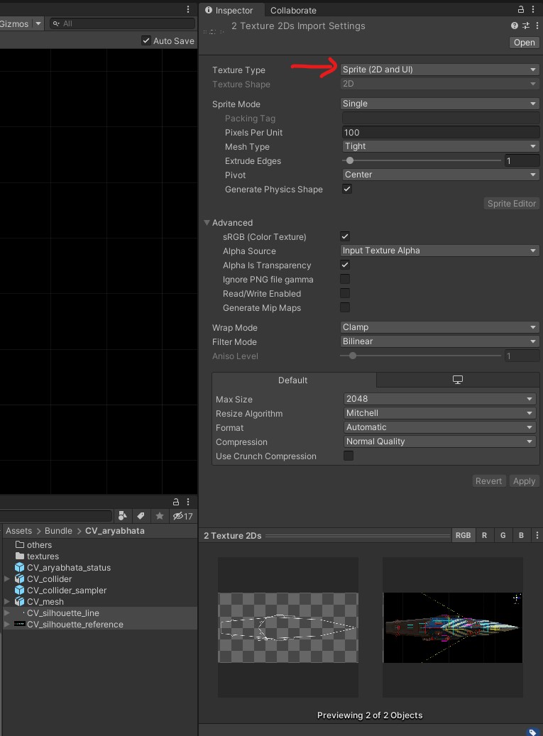
Put those two files in your ship folder and set them both to Sprite (2D and UI) type to make them usable as UI elements.
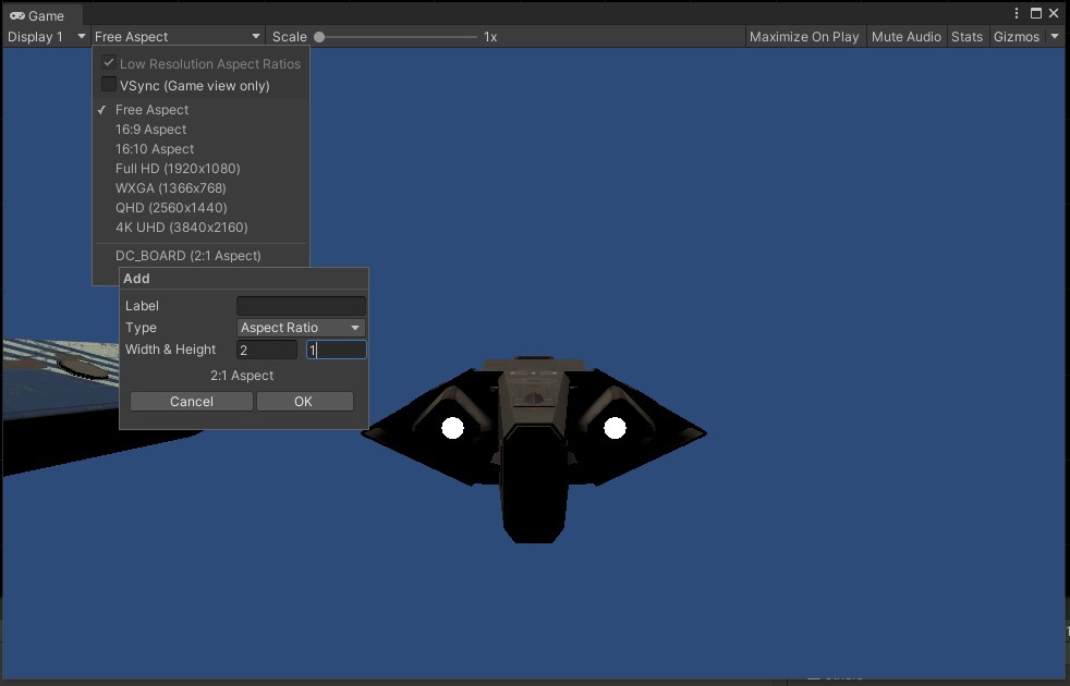
Now here is where things become finicky and require a bit of attention to get right. The UI of the game is scalable, that means DC boards elements placements and sizes are relative to the size of the UI resolution. Thus you need now to open the Window > General > Game window. This window define the proportion of your UI environment, which is a problem since it is freely resizeable and the Status/DC boards require an exact 2:1 ratio. Fortunately you can click on the “+” icon from the Aspect Ration menu to define a custom fixed 2:1 ratio and lock the proportions:
You can drag this window aside as it is not used to display anything.
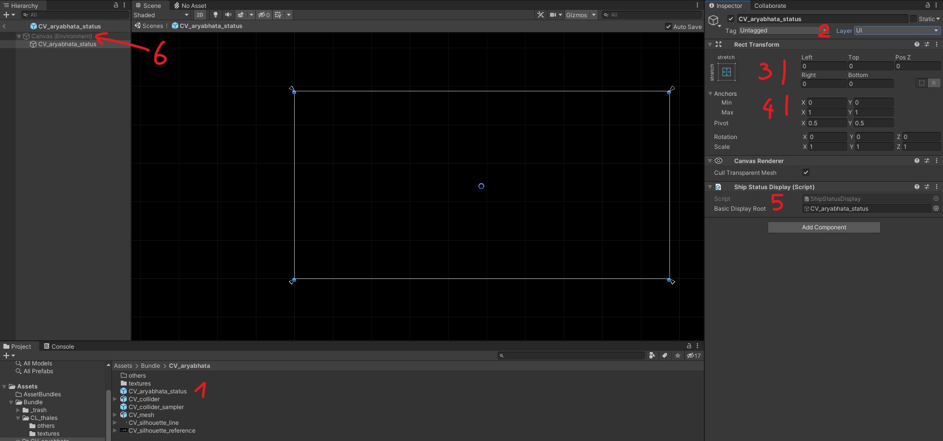
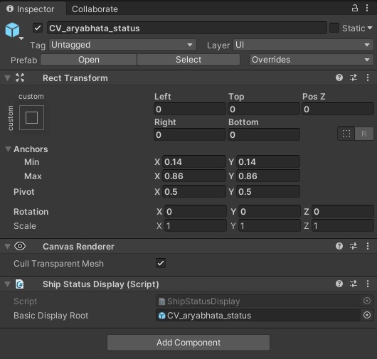
[1] Create a new prefab for the status board
[2] This is a UI layer element, add a Rect Transform component, a Canvas Renderer and a Ship Status Display script.
[3] These values determine pixel offsets for the 2D elements, as mentioned before we need to use relative position to the 2d environment so these 5 should always be 0 for every object within the status and DC board.
[4] The “Anchors” are the relative position values you will have to use to move points around. Often when moving anchor points, pixel values will show up in the offsets at [3] and will have to be set to 0 again. (Do not worry if this is unclear now, it will become evident when manipulating things)
[5] Assign the prefab to the script.
[6] Now this is important: to properly work in 2d environment, you need to close the Status Board prefab and open it again. Once you do that, it will say “Canvas (Environment)” above your prefab and the icon from the Rect Transform will have changed to the one you see to the right.
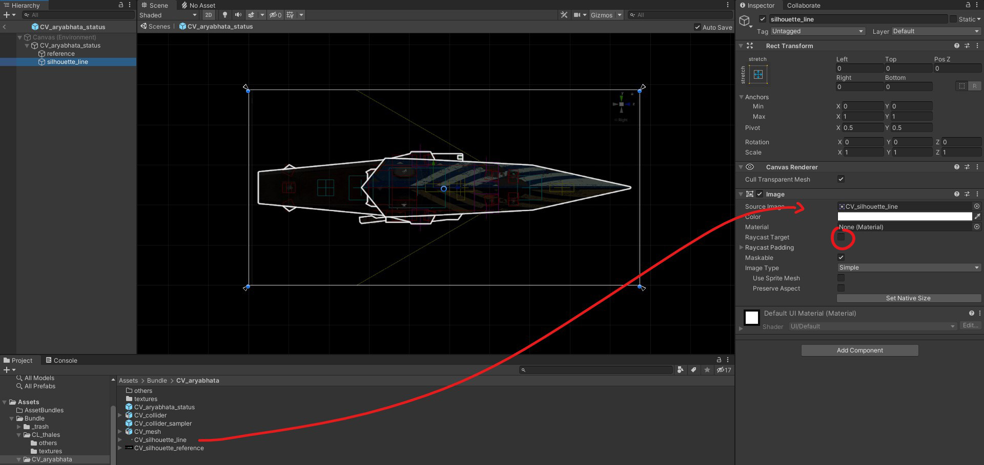
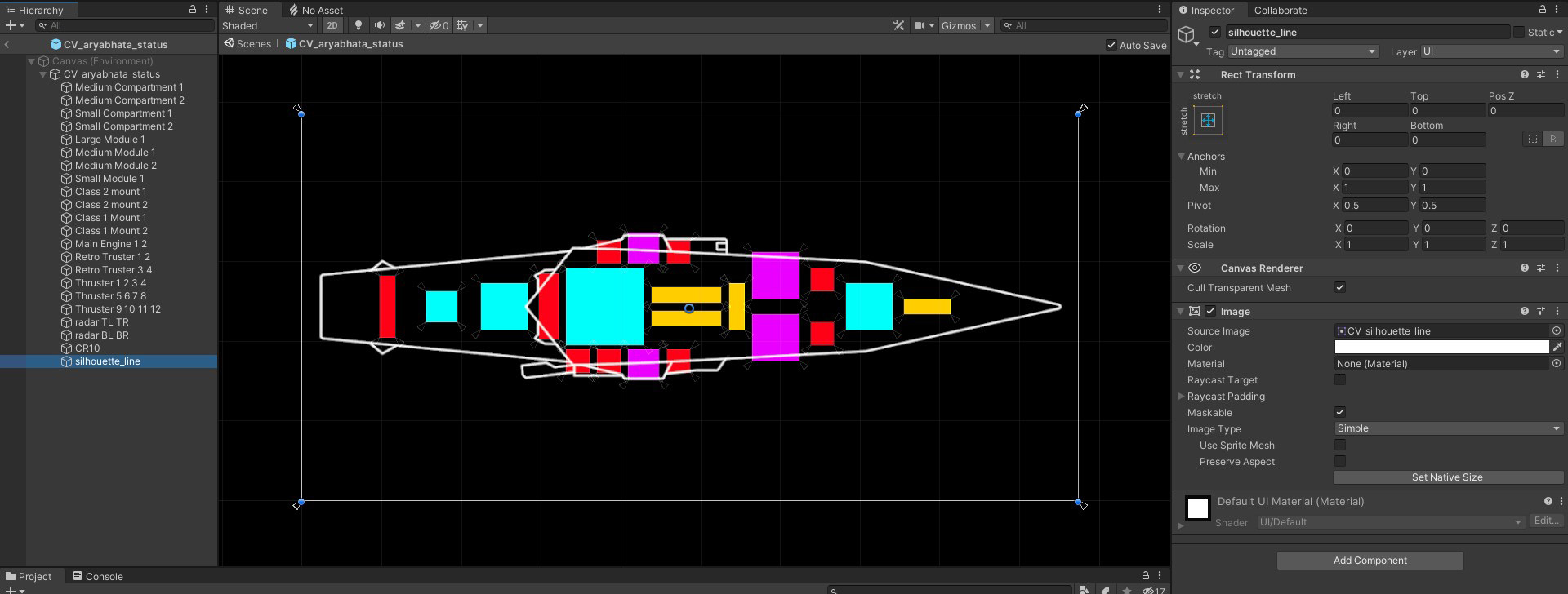
Now create a new object inside the Status board prefab for the reference image. Add an Image component, that will automatically add a Rect Transform and a Canvas Renderer. Link the reference image into the “Source Image” slot, then to stretch that image across the entire Status Board set the Anchors to 0,0,1,1, and all the pixel margins “Left Right Top Bottom” to 0. Repeat this process for the line silhouette. Make sure the silhouette is not a Raycast Target! Objects to the bottom of the list in the prefab are drawn on top.
Note that you can lower the alpha value of the reference image with the Color if needed.
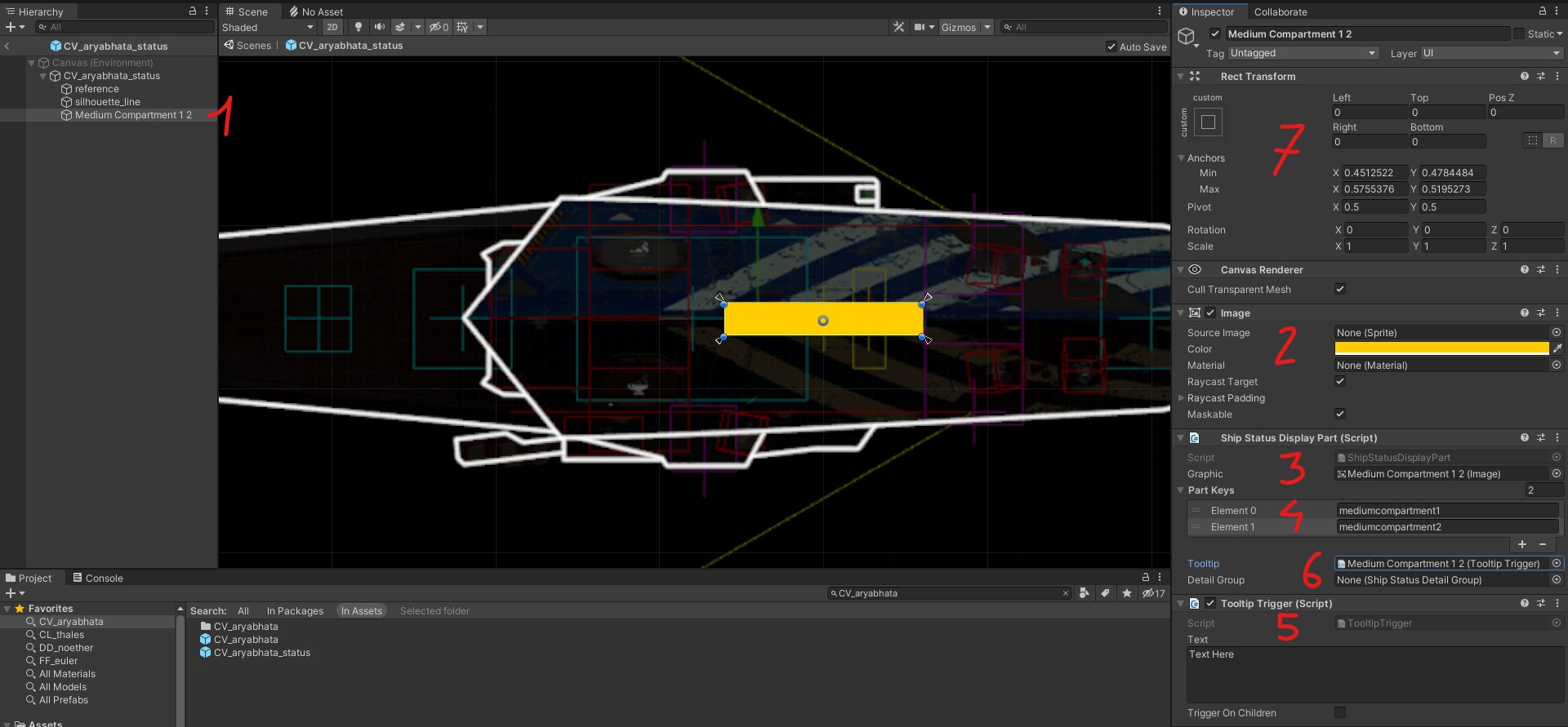
[1] Create a new game object for your first ship socket/subpart.
[2] Add an Image component along the usual Canvas Renderer and Rect Transform. You can change the color of this object since it will be overridden in-game, that can help keeping track of what is what.
[3] Add a Ship Display Part script, drag the Image component to the “Graphic” slot.
[4] This is where the unique socket/subpart Keys from the previous section are being used. Note that you can have more than one part assigned per displayed object. This is often the case for clustered thrusters and engine nozzles, or when two sockets perfectly align.
[5] Add a Tooltip Trigger script (the first one from the list)
[6] Link it in the Ship Status Display Part script
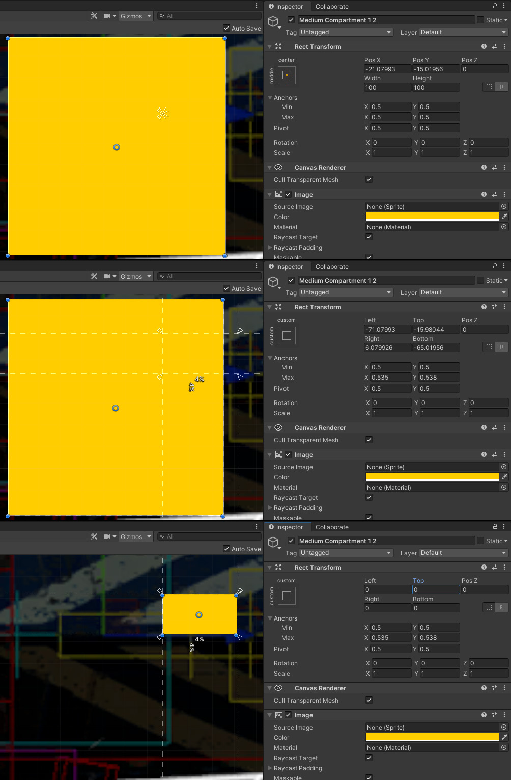
[7] Manipulating those objects is a bit tricky so I will go over this in a bit more details.
The blue dots to the corners of the rectangle are the pixel offsets, those should not be used. Instead you have to manipulate the little white triangles pointing toward the center. Those are the anchor points manipulators.
The non-intuitive aspect of this task is that manipulating the anchors will not change the position of the object and instead add pixel offsets to compensate. Pressing SHIFT will prevent this behavior and move the corners of the object along the anchor points. You can also press SHIFT+CTRL to move all 4 anchors at once.
Once you are done making all the ship’s sockets and subparts, make sure everything is on the UI layer, delete the reference image and move the silhouette object to the bottom of the list so that it is displayed last, and therefore on top of everything else.
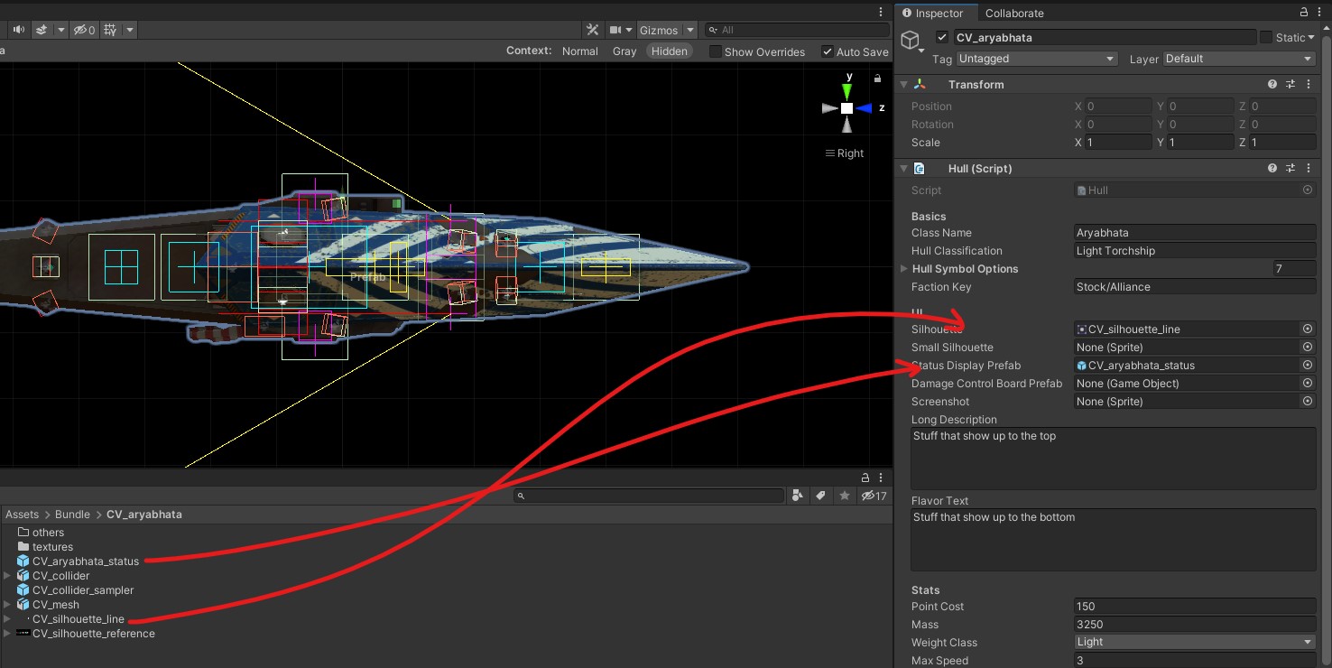
Back on the ship prefab, you can now assign the status board and the silhouette to their respective entries in the UI section of the Hull script.
DAMAGE CONTROL BOARD
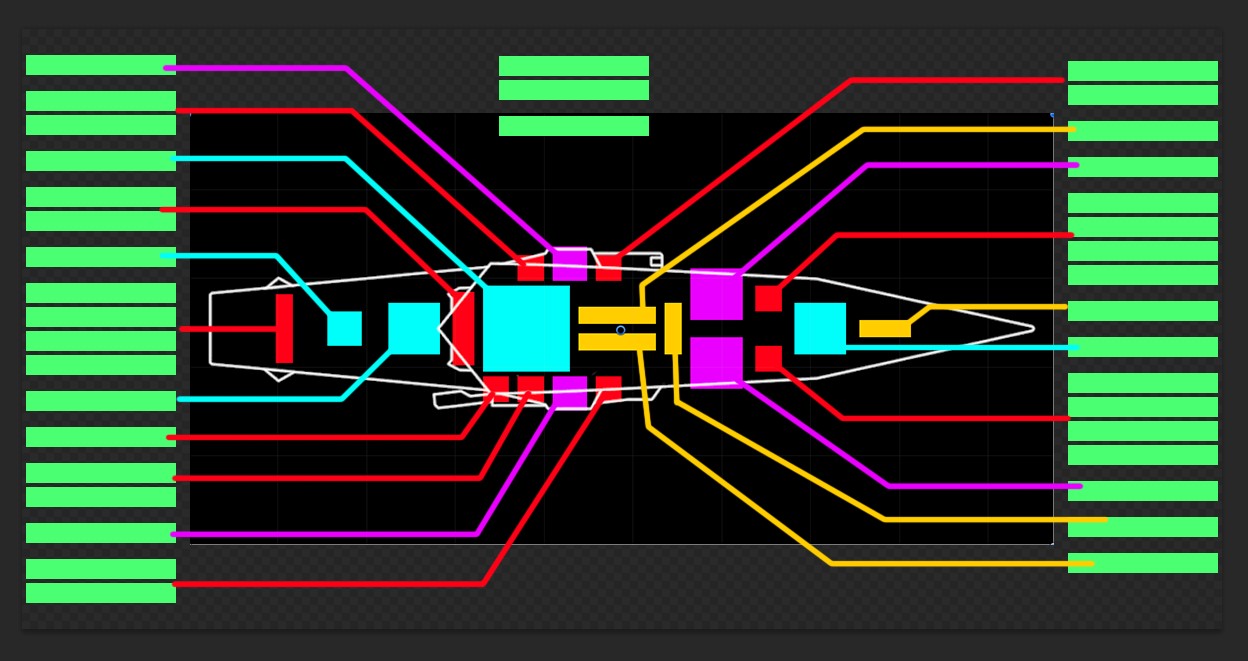
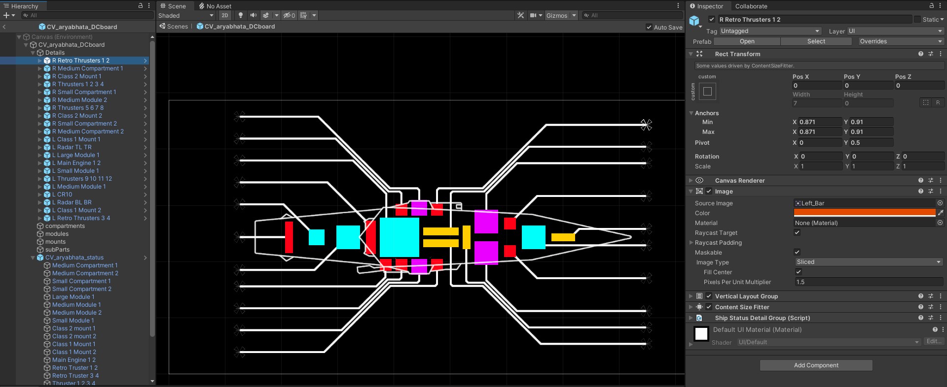
For the DC board you will need sprites with sets of lines linking each of the Compartments, Modules, Mounts, and SubParts to title boxes. Those sprites need to be 1200×600 pixels wide and they will be placed on a downscaled instance of the Status Board. To create them you can use a screenshot of your Status board scaled to a 864×432 resolution. At native resolution, the title boxes are roughly 150×20 pixels wide.
In a 2d editing software I first place my tiles and spread them out on each sides, drawing mockup lines to try and fit everything in that limited space:
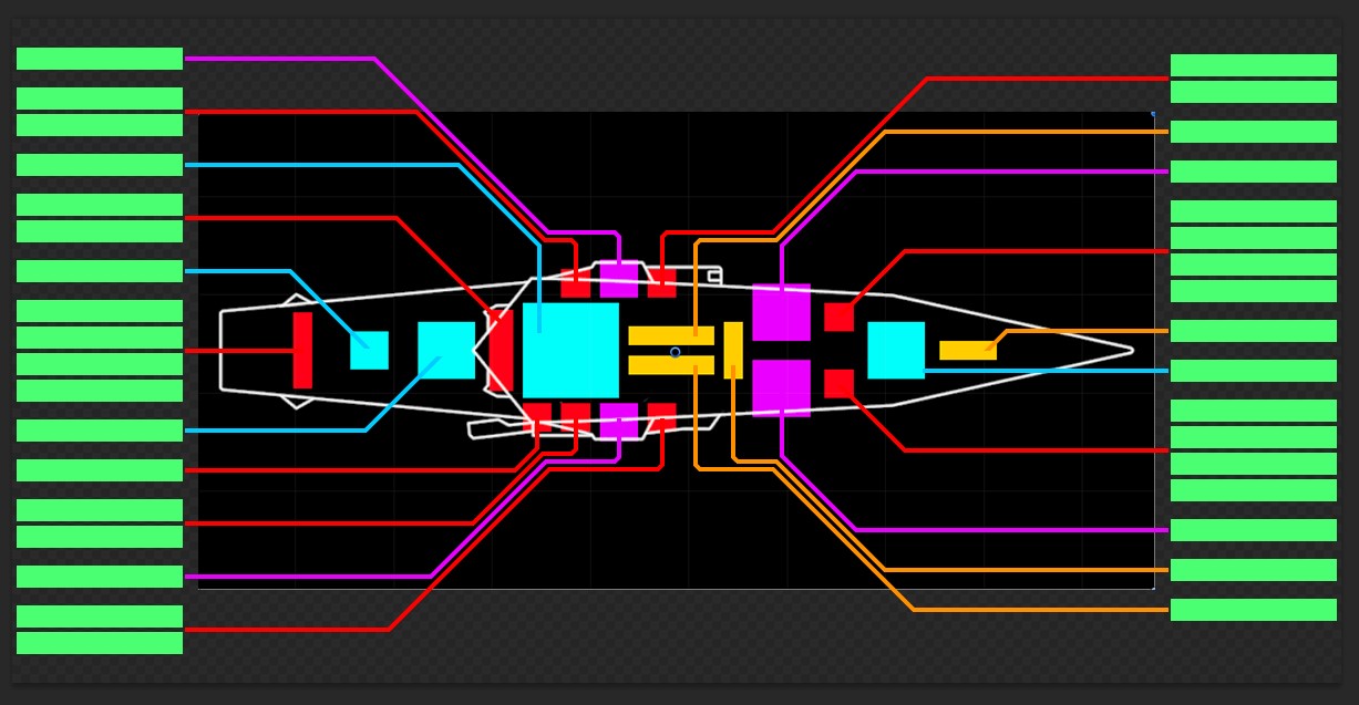
And after cleanup and refinement:
Those lines must be exported as 4 .PNG sprites with Compartments, Modules, Mounts and SubParts separated from each-other.
In Unity, change their type to Sprite (2D and UI) like the silhouette outline before.
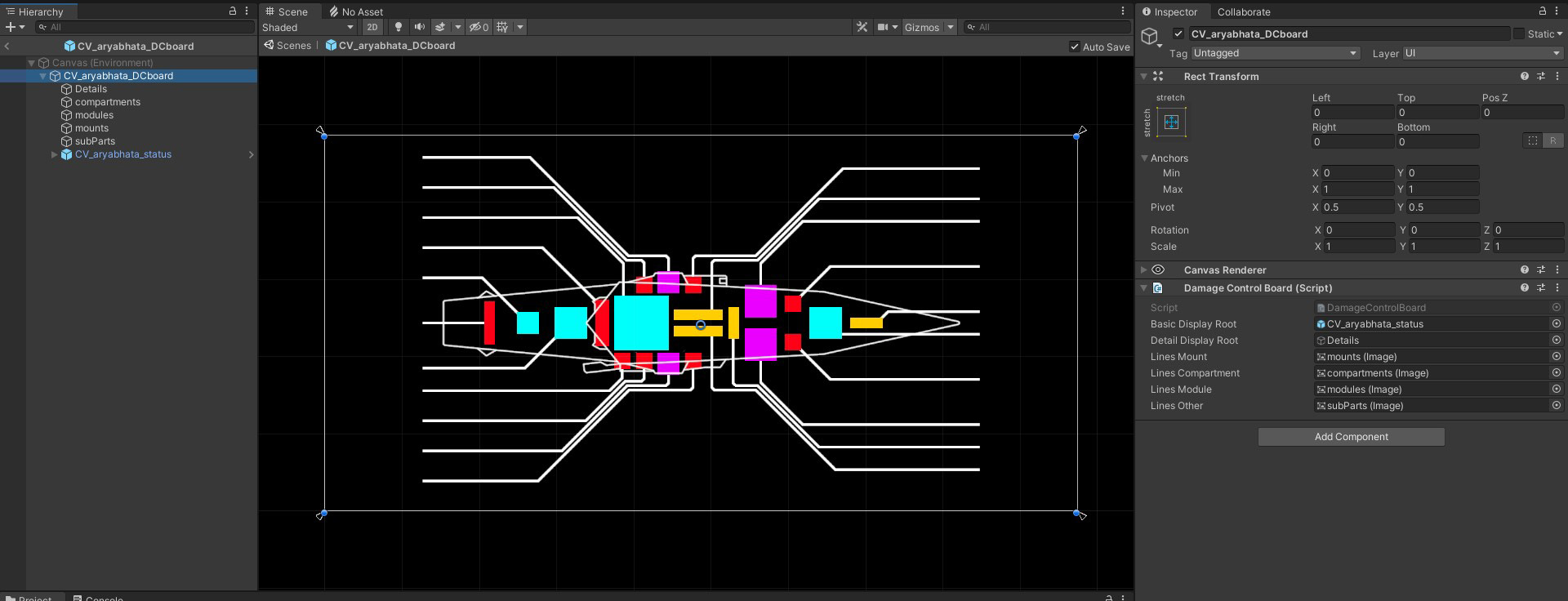
The DC board setup is very similar to the Status board:
You have a prefab with a Canvas renderer and a Rect Transform, edited in “Canvas (Environment)” mode.
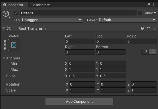
The “Details” object is empty (for now) with only a Rect Transform:
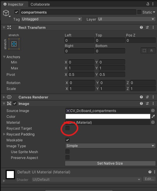
The compartments, modules, mounts and subparts object are there to display the lines:
The Raycast Target must be un-ticked otherwise the DC Board will not react to the mouse when inside the area of the sprites.
And you can drop the Status Board prefab to the bottom:
Make sure to set the same Anchors values for this one.
All these elements need to be slotted into the Damage Control Board script on the DC board prefab.
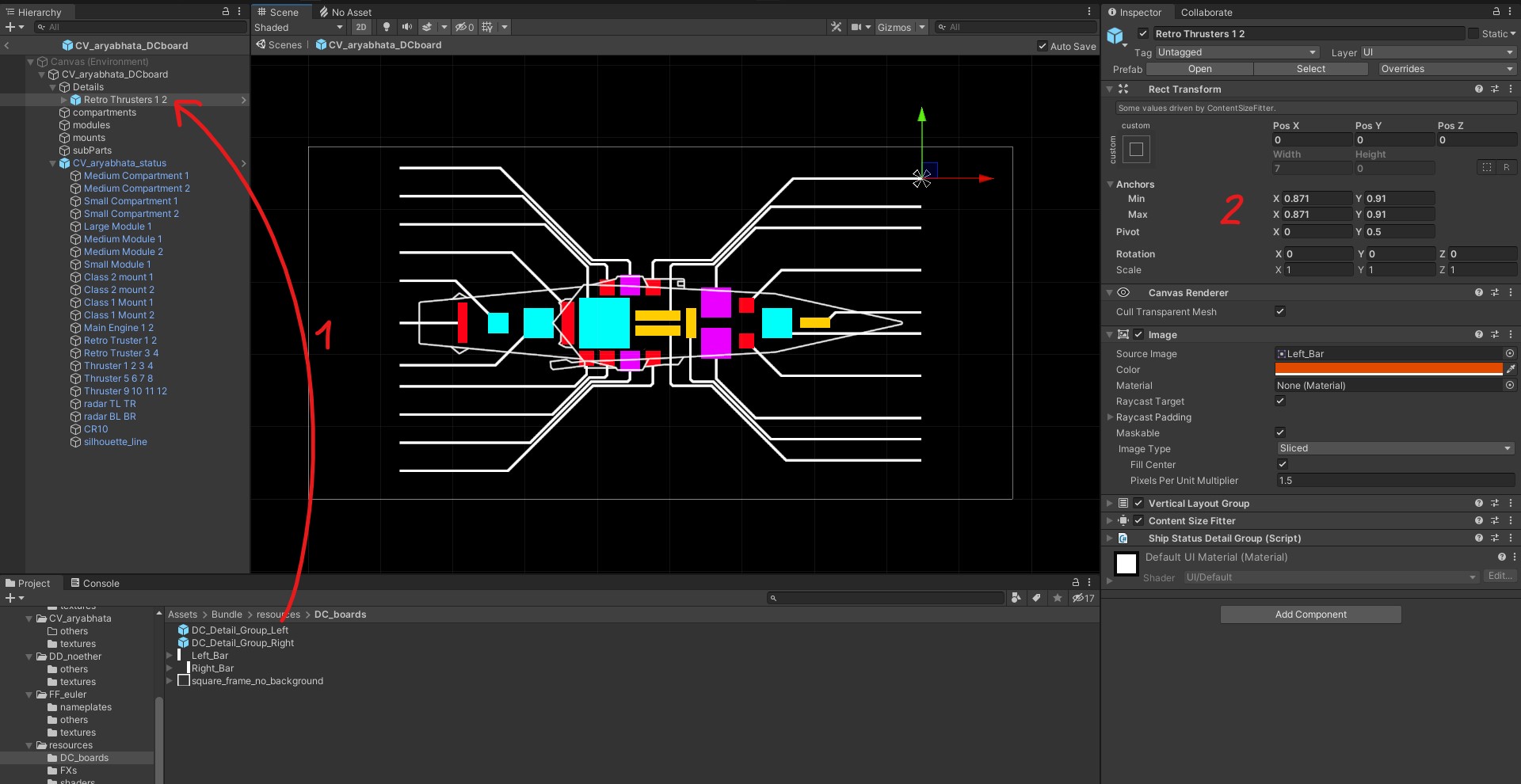
[1] From the provided resources/DC_boards prefabs, drop appropriate DC_Detail_Group_Left and DC_Detail_Group_Right prefabs into the “Details” object.
[2] Place them at the tip of the line with 0 surface area. Left detail groups will unfold to the left and conversely for the right ones.
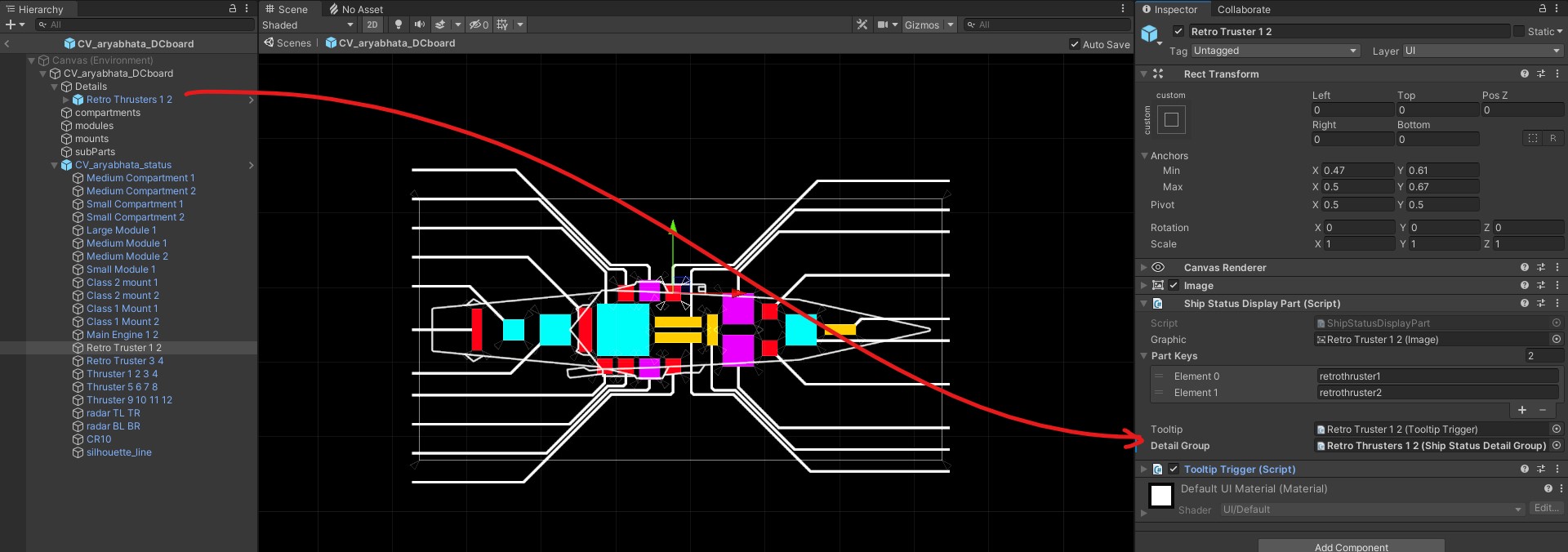
That prefab can then be slotted into the Detail Group entry from the Ship Status Display script of the related Status Board object:
Now repeat until every line has a detail object assigned and all the Detail Group entries are populated. Make sure everything is on the UI layer.
Lastly you can slot the DC Board prefab into the Hull script from your ship prefab:
There, you are done with the DC Board!
NAMEPLATES
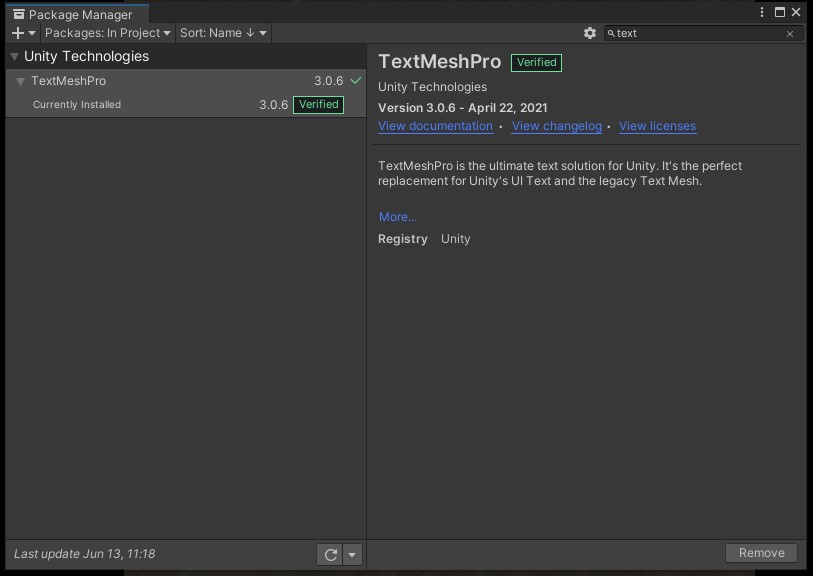
For this section you will need to install the Text Mesh Pro package. Go to “Window / Package Manager” and use the search function to enable it.
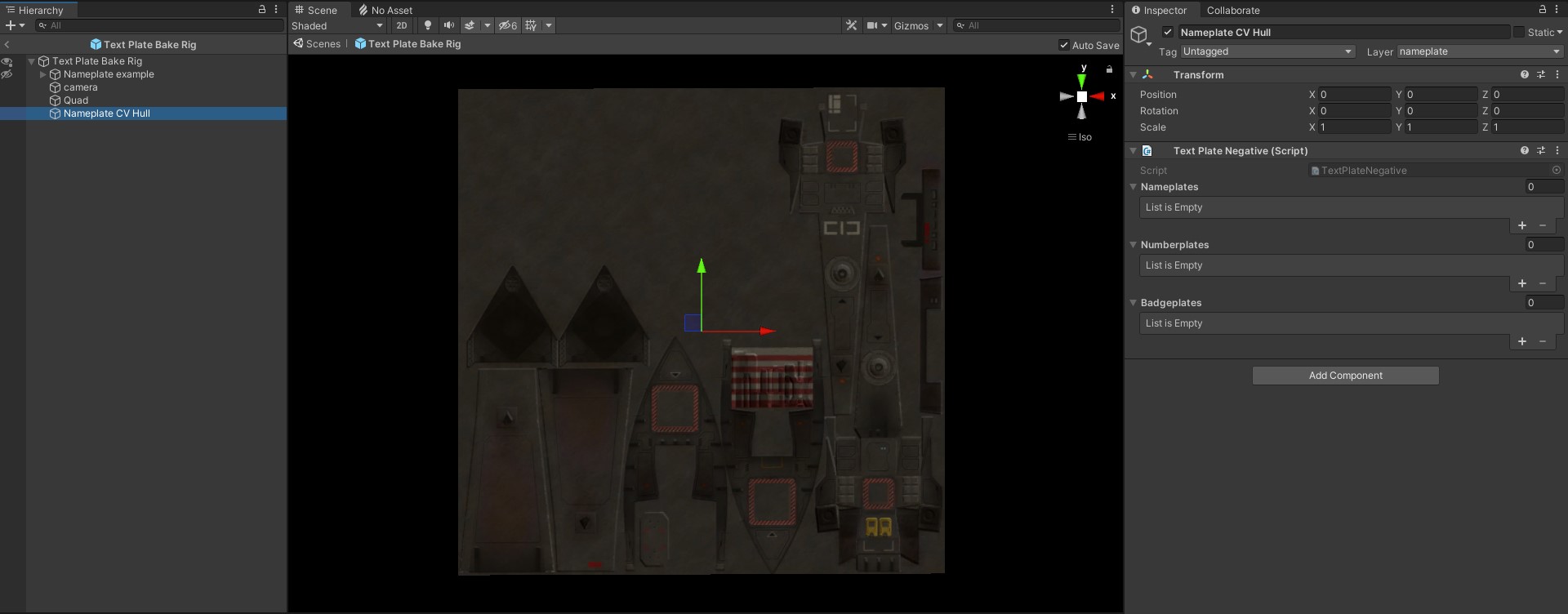
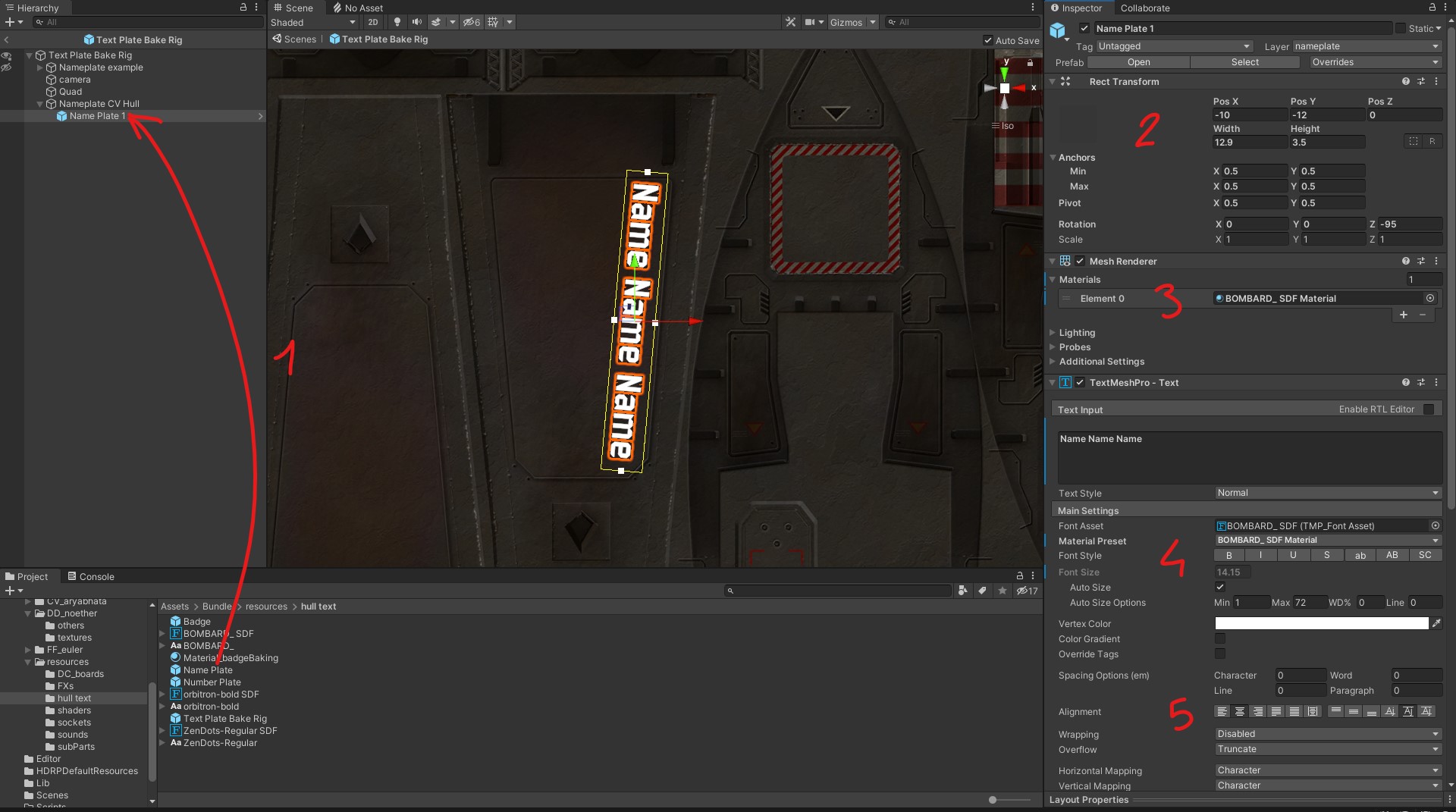
In “resources/hull text” you will find a Text Plate Bake Rig prefab that is used to place the nameplates onto your texture. Create an object for your first hull segment that will have texts, 0 its transforms and add a Text Plate Negative script. Assign the material of that hull segment to the Quad.
[1] Drag as you see fit “Badge”, “Name Plate” and “Number Plate” prefabs into your nameplate object.
[2] Place them onto your texture. “Name Plate” Width and Height control the maximum space that can be used by the ship name, while the size of the “Badge” is determined by the Scale. The size of the “Number Plate” on the other hand is set by the font size.
[3] Choose your font style, I made two available but we will see how to import new fonts next.
[4] You can change the style of the font
[5] And you can change the alignment. This can be useful for example, if you want your Number plate always justified to one side, or your ship Name to have a constant margin to the top regardless of the automatic font size.
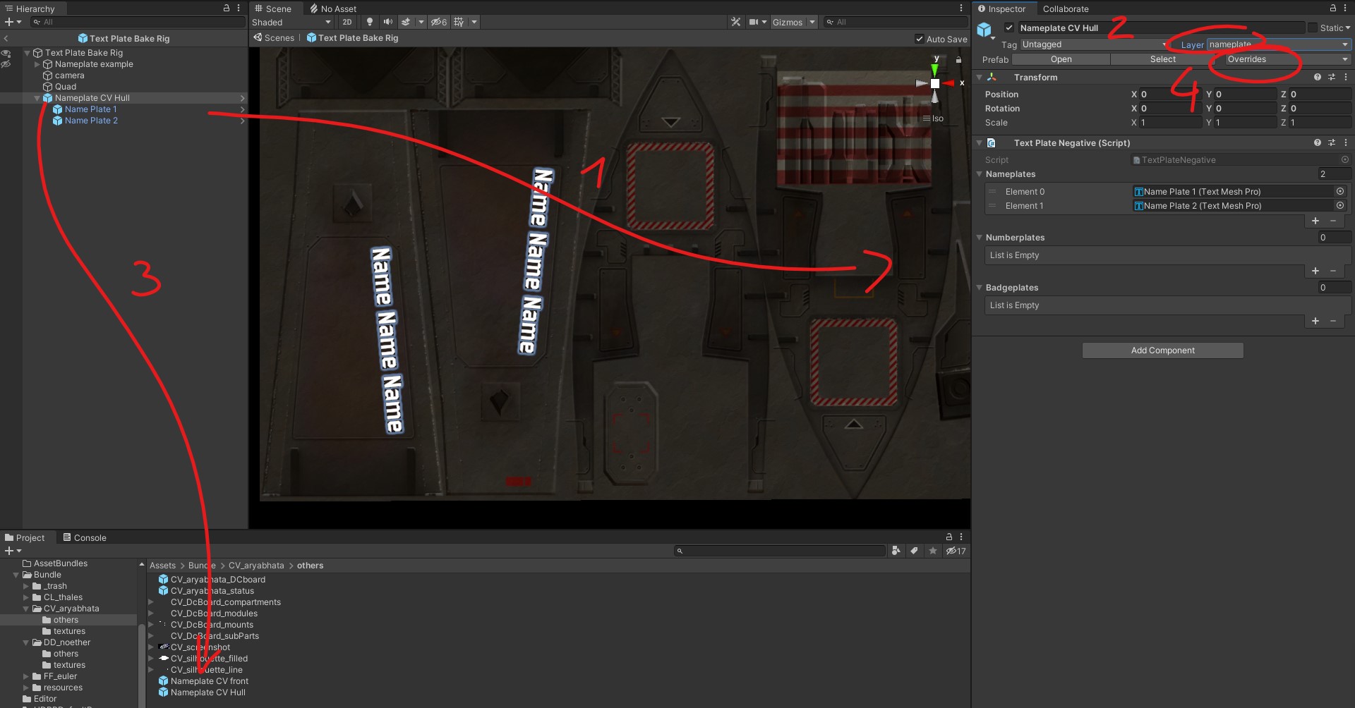
[1] Once you are done placing the names, numbers and badges, slot them into the Text Plate Negative script from your nameplate object.
[2] Make sure that object is on the Layer 16, create it if needed.
[3] Now you can turn the nameplate object into a prefab in your ship folder, and remove it from the Text Plate Baking Rig prefab to avoid clutter.
[4] If you have to make adjustments late on, remember to apply the changes to the prefab via the override menu.
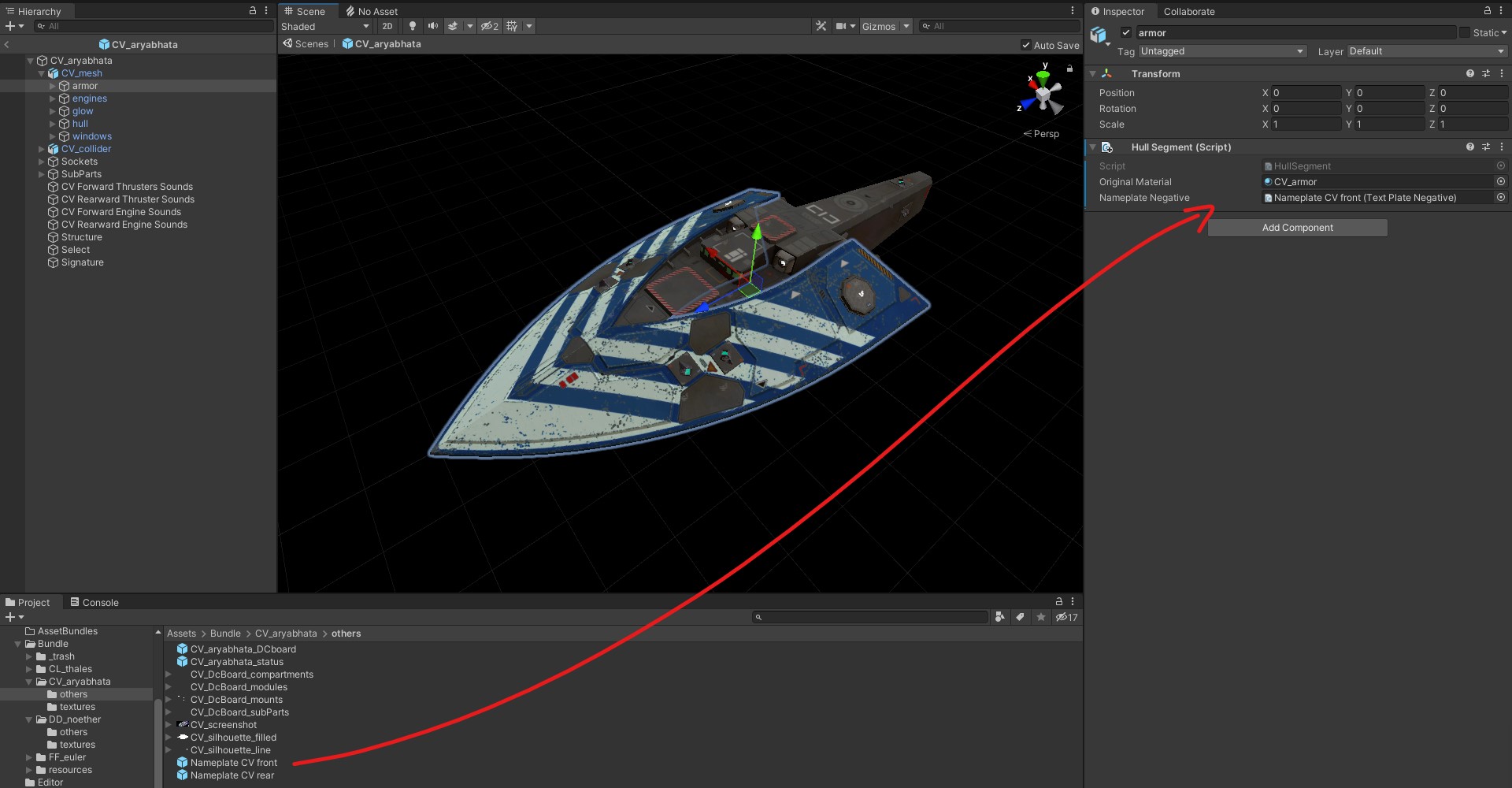
Back on the ship prefab, slot that Nameplate prefab into the Hull Segment script from the relevant mesh group.
Note that only “Paintable” meshes can receive Nameplates, you may need to add those segment to the relevant list from the ship prefab’s Hull script.
Unfortunately, due to the baking process of custom names, those texts are only visible once in the game and not in Unity.
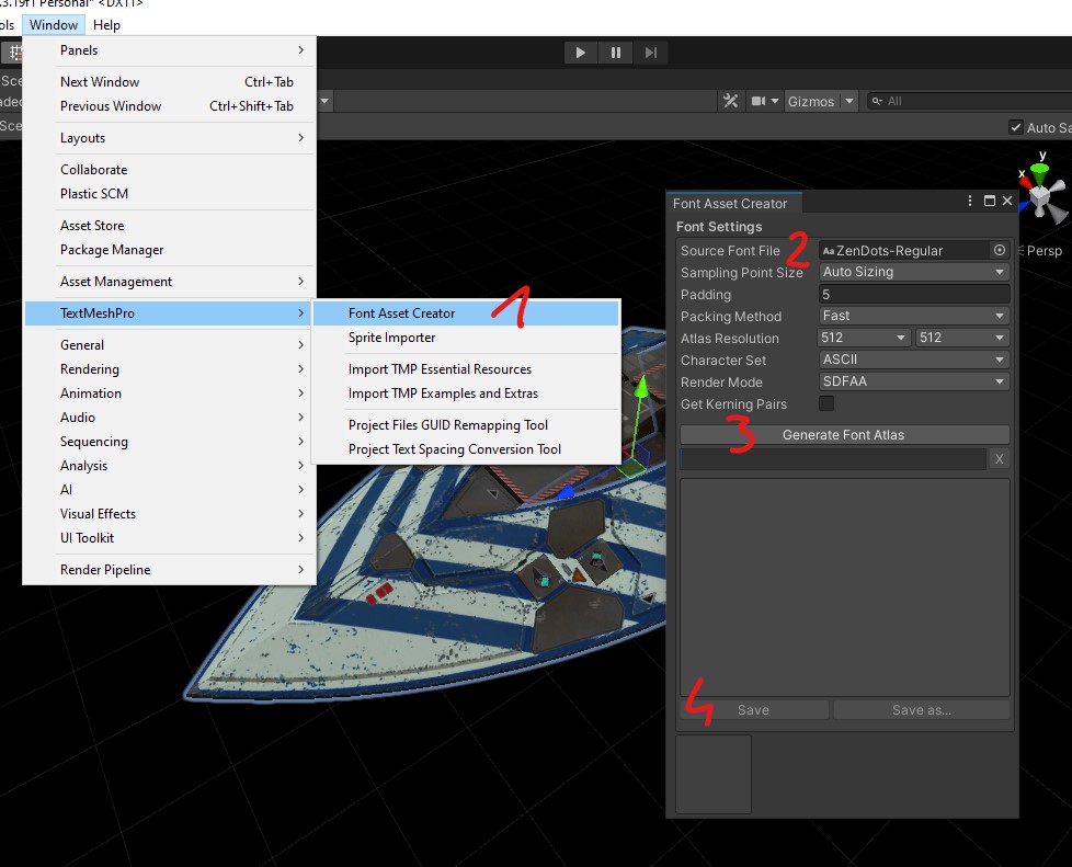
To use a custom font you need to build an atlas for it:
[1] Open the Font Asset Creator
[2] Copy your font .TTF file into your project, and load it in the tool
[3] Generate,
[4] and save.
FINISHING
The bulk of the work is done, but there are a few quick things to add:
Placing Sound emitters
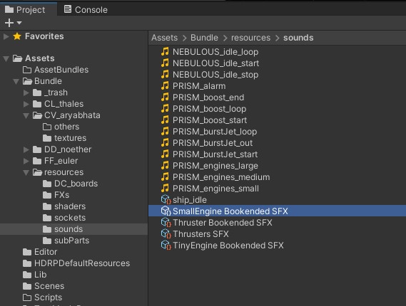
Your engines need sounds. You will find some in the sounds section of the provided “resources” folder, but here are some details about what they are for when you will to make your own.
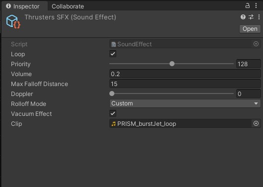
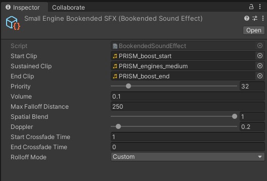
There are two types of sound constructs used with ships:
straight loop SFX,
and Bookended SFX.
Bookended sounds automatically blend intro, loop and outro sounds into one object.
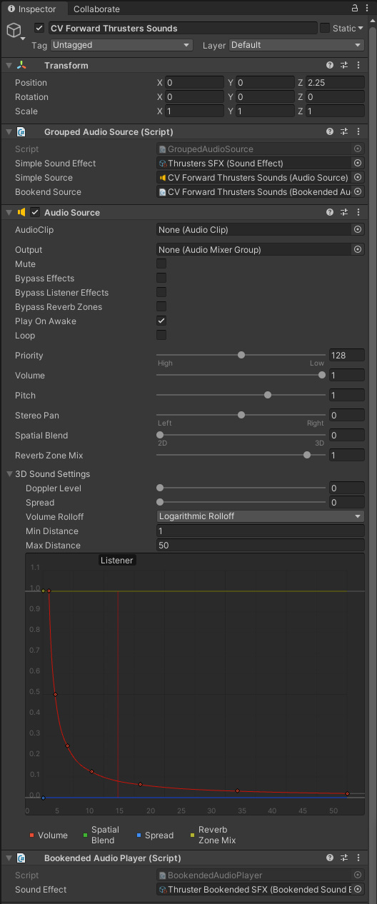
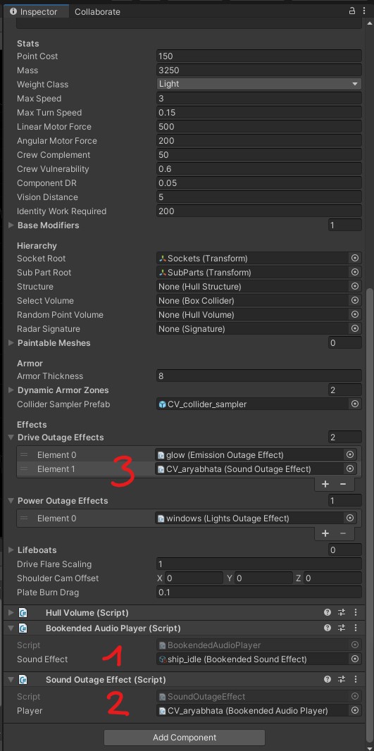
Now you need to add sound emitter objects to your ship prefab, one for each sound type, or multiple if there are multiple locations. In practice most ships will have two “main engine” sound emitters for the rear and bow engines, and two “thrusters” sound emitters for the bow and aft rings of thrusters.
The Audio Source component manages the range of the sound. Make sure to set the Doppler Level to 0 and to properly set the Max Distance to around 50 for the thrusters, 100 for the bow engines and 250 for the main engines.
The rear and bow engines are the same thing only using the appropriate engine sound in the Bookended Audio Player script
Once your various emitters are created and placed, you can assign them to the Thruster Part script from all the relevant SubParts.
Back to the ship prefab, you can also fill out the empty sounds components and Hull script entry:
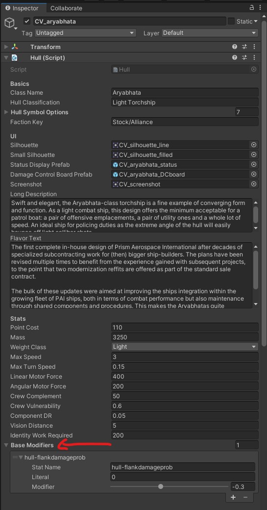
Hull Bonuses
You can give special bonuses to your ship to add flavor. Those are added in the Base Modifiers list of the ship prefab’s Hull script.
Here is the list of attributes that can be modified
component-maxhp
component-dr
component-workspeed
component-raredebuffchance
powerplant-prodefficiency
damagecontrol-movespeed
damagecontrol-repairspeed
intel-effort
intel-accuracy
comms-power
comms-bandwidth
comms-gain
continuousweapon-burstduration
continuousweapon-cooldown
continuousweapon-overheatdamageprob
continuousweapon-directdamagemultiplier
tubelauncher-reload
turret-traverse
turret-elevate
muzzle-accuracy
discreteweapon-recycle
discreteweapon-reload
sensor-maxrange
sensor-power
sensor-gain
sensor-aperture
sensor-maxposerror
sensor-maxvelerror
sensor-sensitivity
sensor-lockmultiplier
sensor-minlocksnr
sensor-burnthrupowermultiplier
sensor-burnthrudamageprob
hull-mass
hull-maxspeed
hull-turnrate
hull-linearmotor
hull-angularmotor
hull-sigmult-radar
hull-crewvuln
hull-armorthickness
hull-componentdr
hull-visiondistance
hull-flankdamageprob
hull-identificationwork
hull-crew-cheer
hull-structurehp
Note that the in-game name of the modifier can be confusing, for example the “damagecontrol-movespeed” attribute will show up as “Team Move Speed” which could be interpreted as a speed bonus for the fleet.
Miscellanies
Okay, last stretch!
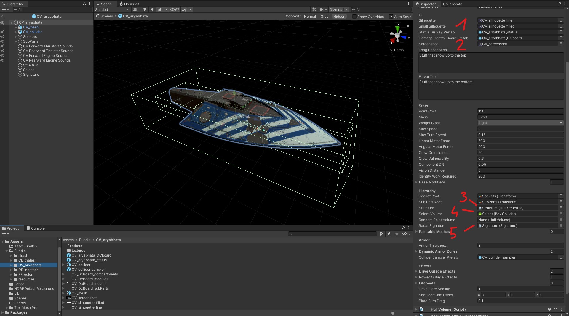
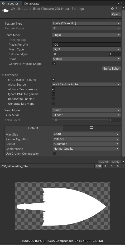
[1] The small silhouette is a small Sprite (2D and UI) image that is used in the sensor screen in-game and to select a hull in the Ship Editor list. It is a .PNG of 400×200 resolution of your ship silhouette in white on transparent background. Note that it is used to identify your ship at glance, thus should be iconic.
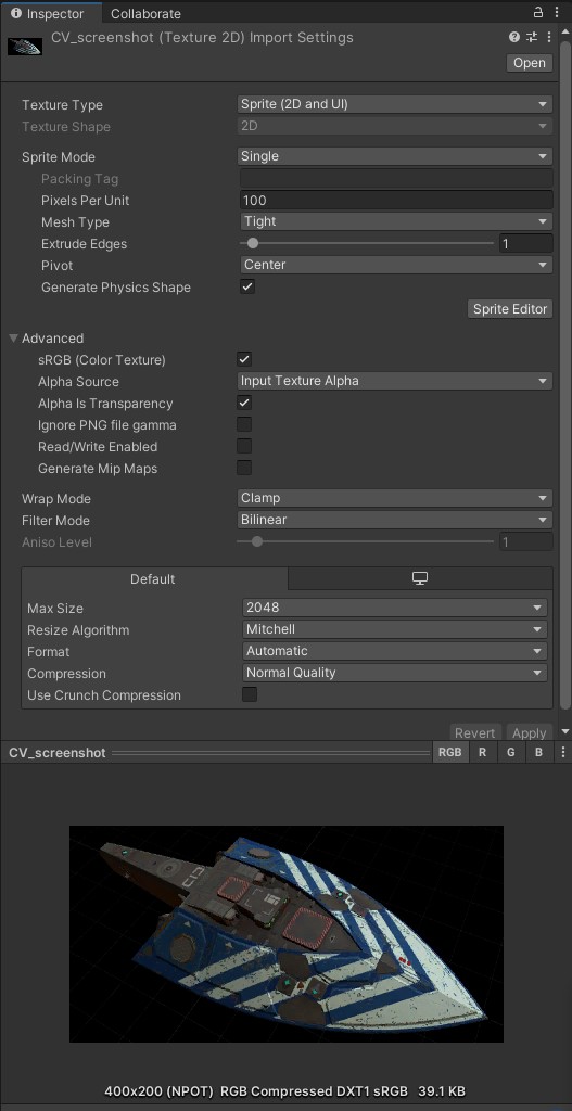
[2] The screenshot is a small Sprite (2D and UI) image that is used in the Ship Editor list. It is a .PNG of 400×200 resolution of your ship in action (and thus will have to be re-done once you get it ingame)
[3] The Structure is a simple object with a Collider component and a Hull Structure script. The collider does not need to perfectly match the shape of the ship, only a rough volume of it and must be entirely inside the hull to get damaged by shot that penetrate the armor. It needs to be on the layer 11, the same as the sockets.
[4] The Select Volume is the object that detect a mouse click to select the ship ingame. That object requires a Collider component, a Dynamic Visible Hierarchy script and to be set on the PostProcessing layer.
[5] The Radar Signature is the object used to calculate the radar cross section of the ship. Unfortunately, we do not have access to the plugin used with vanilla ships to sample the cross section from the collision model. We are left to make coarse approximations using a basic Collider volume. Note that the shape does not necessarily have to represent that of the ship: here I’m trying to reduce the signature from the front while maintaining a roughly equivalent cross section area from the sides and top.
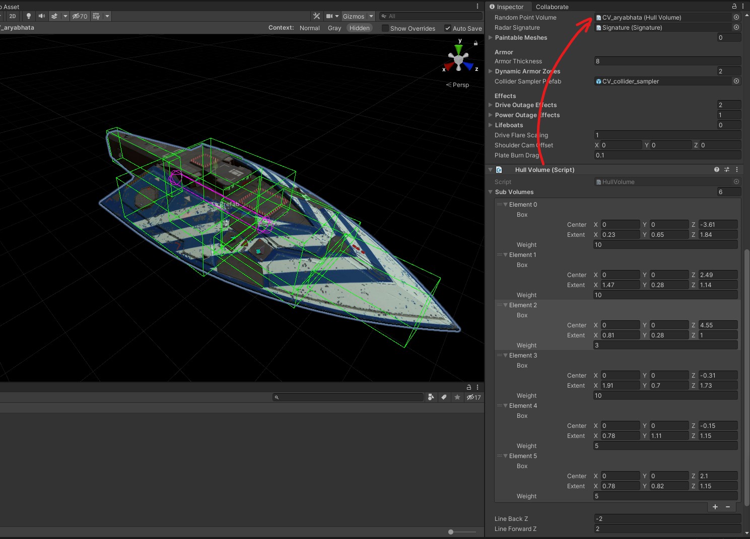
Then you have to setup the Sub Volumes for the Hull Volume script on the ship prefab:
Those elements represent volumes that will be targeted by enemy fire, they should represent an approximation of your ship volume.
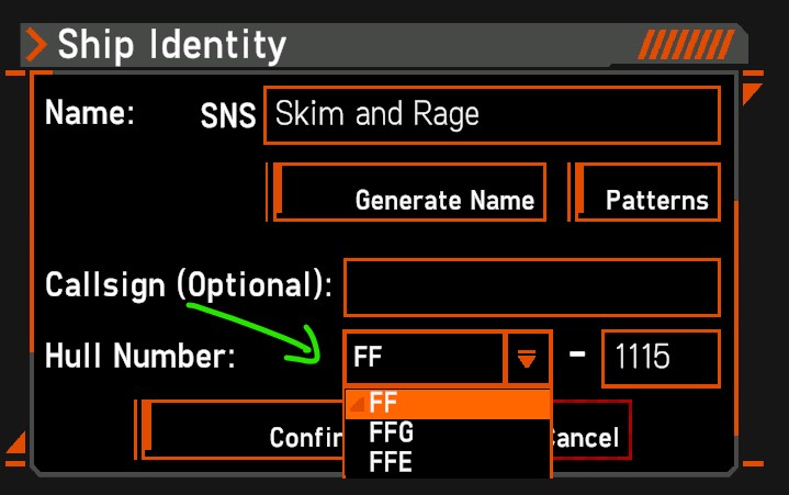
Finally, when naming your ship you have access to a list of hull designations:
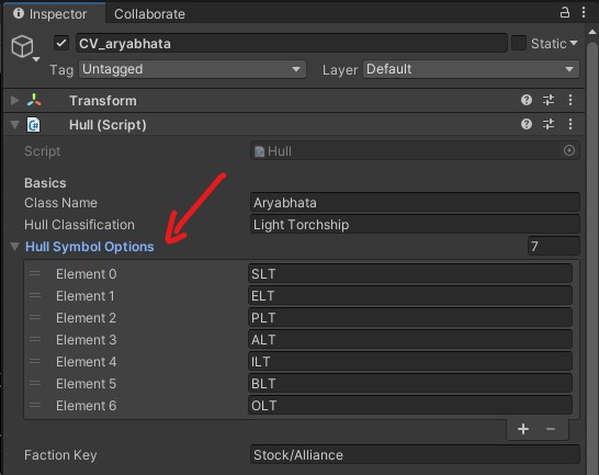
Those are defined in the ship prefab’s Hull script:
GETTING THE MOD IN THE GAME
This is the final step to get your ship in the game:
If you properly followed the Official Modding Guide, you can make use of the Build AssetBundles script. Make sure your ship prefab as well as the ship folder are part of your mod’s Asset Bundle then Build up the thing!!!
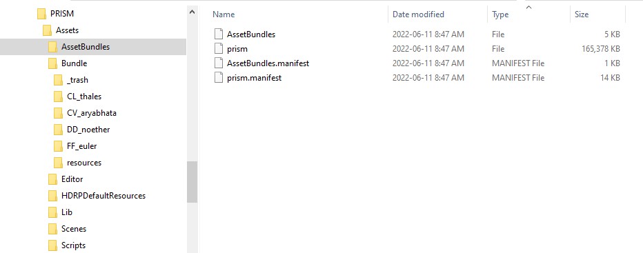
If everything goes right, you will see files popping up in the AssetBundles folder from your project directory:
You can now copy those files into your mod’s folder inside “Nebulous/Mods”:
Make sure your Asset Bundle is registered in the ModInfo.xml file at the root of your mod folder:
<?xml version="1.0"?>
<ModInfo xmlns:xsd="http://www.w3.org/2001/XMLSchema" - []  xmlns:xsi="http://www.w3.org/2001/XMLSchema-instance"> - []
 <ModName>PRISM Aerospace International</ModName>
 <ModDescription>A collection of ships</ModDescription>
 <ModVer>0.1.43</ModVer>
 <AssetBundles>
 <string>prism</string>
 </AssetBundles>
 <PreviewImage>C:\Steam\steamapps\common\Nebulous\Mods\PRISM\PRISM Aerospace International.jpg</PreviewImage>
 <GameVer>0.1.0</GameVer>
</ModInfo>
(notice the optional <PreviewImage> line allowing you to upload a thumbnail to the workshop)
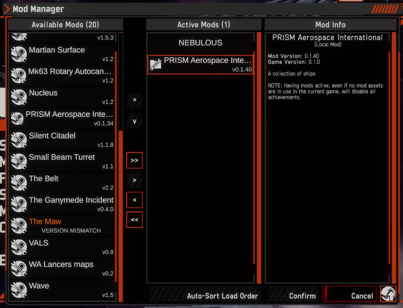
Launch the game, do not let your heart skip a bit because you forgot to enable the mod in the mod manager:
Now cross your fingers real hard and restart the game!
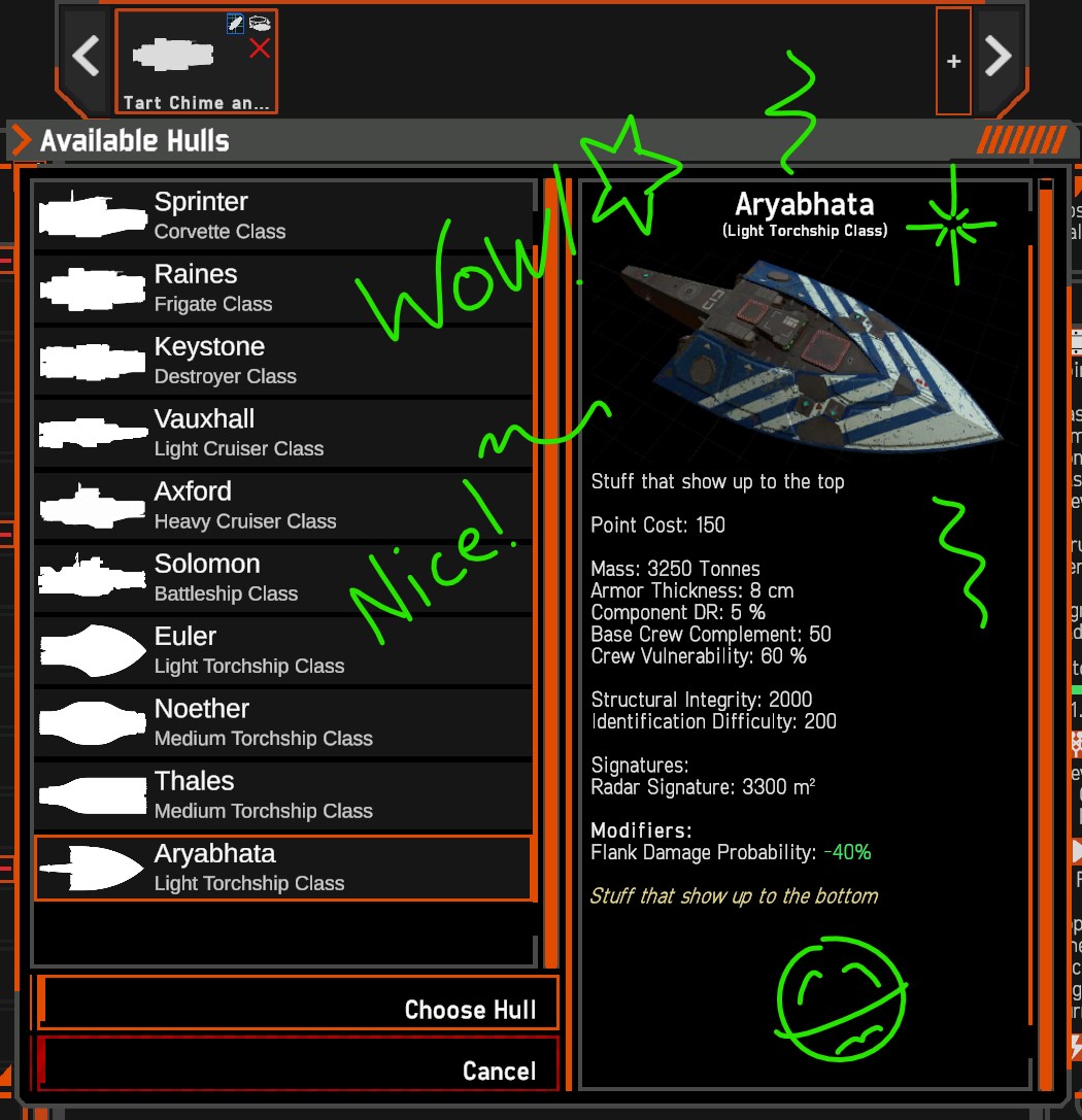
And hopefully you will see something like this:
To be honest though, it usually takes a couple of tries: even after insisting on double checking everything throughout this guide, I managed to NOT assign my ship prefab to the Asset Bundle on the first build, and to mess up one hull component Key… So yeah do not be surprised if it takes a two tries or five to build a working mod even after several ships.
I hope this guide was helpful and I am eagerly waiting for new ships to show up in the game!
Here we come to an end for NEBULOUS: Fleet Command Official Guide – Walkthrough hope you enjoy it. If you think we forget something to include or we should make an update to the post let us know via comment, and we will fix it asap! Thanks and have a great day!
- Check All NEBULOUS: Fleet Command Posts List

















Leave a Reply