
A simple introduction to the logic devices in Evospace as at version 0.18.2
Overview
Evospace includes some basic logic components that can make your Evospace life easier and more efficient. Once you can create steel and research the required technologies you can control switches, valves and machines using logic.
The devices
The basic devices are:
- Logic Interface– this reads information from a device or storage
- Logic Controller – this allows a switch or device to be controlled by logic signals
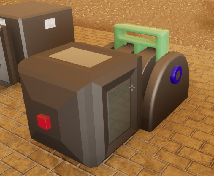
- Logic Circuit – this contains the logic rules that allow signals to be sent to a controller or display
- Logic Display – this displays numbers, colours or other detail based on logic signals
- Logic Wire – this conveys logic signals between all the various types of logic devices
The inputs and outputs are colour-coded green for output and red for input.
Logic interface
The logic interface is used to read information from a device or storage.
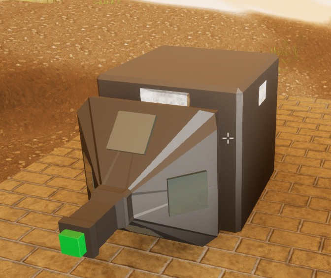
]In this example the logic interface is connected to a stone chest.
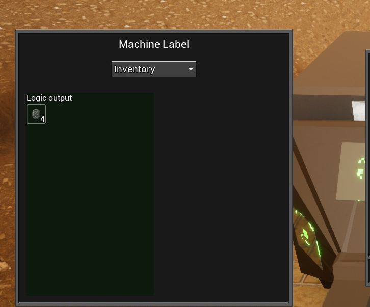
If you select the option “Inventory” you will get a signal of an object type and quantity. In this example the chest contains 4 pieces of coke.
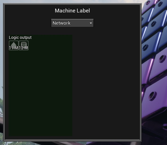
In this example the logic interface is connected to a fluid storage. Instead of “Inventory” you select “Network” and you will get a signal of the total amount of fluid and the total amount of storage.
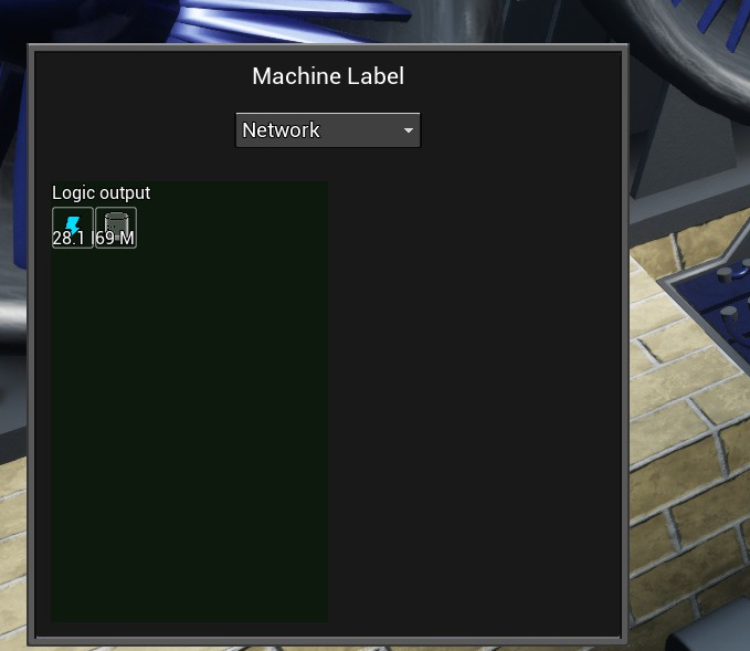
In this example the logic interface is connected to a battery box. This is showing the total power and total amount of storage.
Note: When the signals from all the interfaces on a network are combined all cumulative storage is added together; all the different types of fluid storage and the power storage. Take care when calculating what proportion of storage space is left.
Logic controller
The logic controller is used to control switches, valves and machines.
In this example a logic controller is attached to a switch.
Logic circuit
The logic circuit can perform simple calculations based on inputs from the green input side and return results through the red output side.
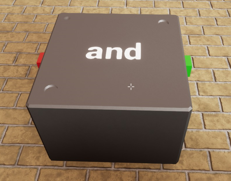
In this example the function is set to “and”. However it needs to be connected to logic wire or devices to be useful.
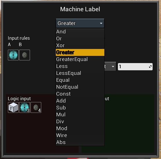
Here is a list of the available functions.
The “Logic input” section shows the signals that are available on the wire connected to the red (input) side. The variables are represented by items rather than text.
The “Input rules” section is where you select which of the input variables from the “Logic input” section you want to operate on.
Logic wire
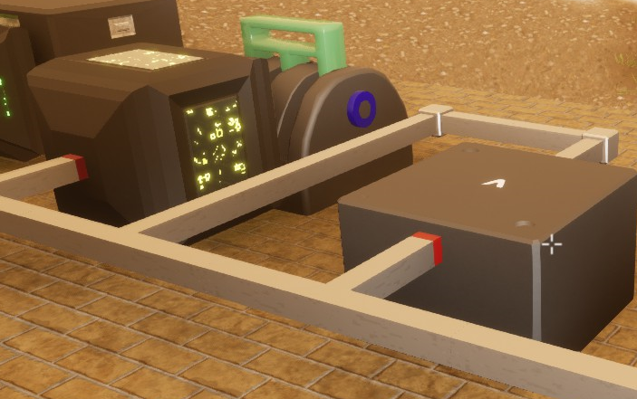
The logic wire is used to carry signals between logic devices.
The logic wire below is carrying the signal between alogic circuitand logic controller as part of a larger logic network.
Example of a switch controller
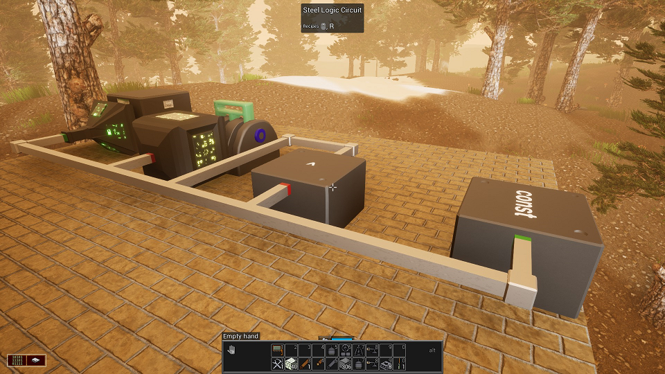
This is a simple example of a switch being controlled by the number of items in an inventory.
The logic network is comprised of (from left to right):
- logic interface – connected to a stone chest that has the items we want to measure
- logic controller – connected to a switch that we want to turn on or off depending on the number of items in the chest
- logic circuit 1 – set to a “greater than” (>) function to compare the items in the chest to the value to activate the switch
- logic circuit 2 – set to a “const” function that will be used to set the value to activate the switch
- logic wire – all devices are connected to the wire.
Note that logic circuit 1 (>) has wire connected to the input as well as output whereas logic circuit 2 (const) only has wire to the output. This is because logic circuit 2 does not require input to generate a constant value.
Step 1 – Stone Chest
First there is a stone chest that contains four pieces of coke. We connect a logic interface to the chest and select the “inventory” function. This is displayed in the “Logic output” section of the user interface as the variable coke with a value of four..
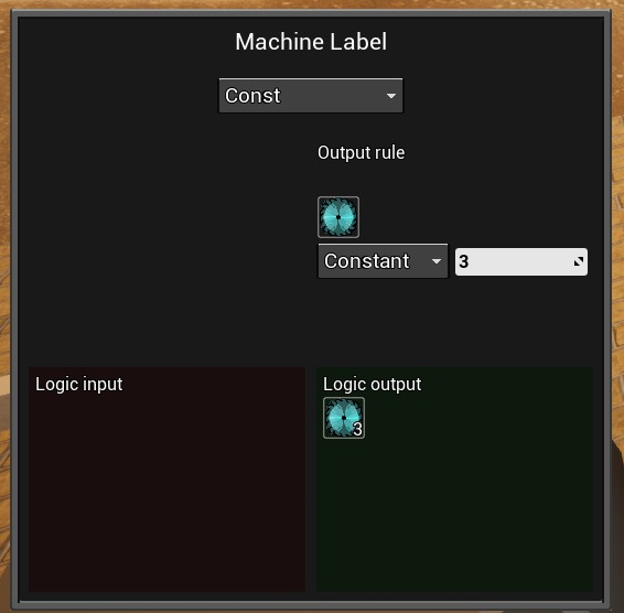
Step 2 – Logic Circuit – const
Logic circuit 2 has been set to “const” function. For the output rule I selected the aluminium cutter as the variable. It does not matter which symbol you select to represent the variable. I have set the value to three. This is represented in the “Logic output” section of the user interface.
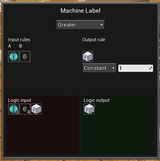
Step 3 – Logic Circuit – Greater
Logic circuit 1 has been set to the “Greater” function. The “Logic input” section shows all of the signals that are on the logic wire that is connected to the input. They are:
- Aluminium cutter with a value of 3. This signal is received from Logic circuit 2.
- Coke with a value of 4. This signal is received from the logic interface that is connected to the stone chest.
- Stainless steel fermenter. This signal is derived from the Output rule.
For the Input rules I selected two values from the available “Logic input” signals. They are the aluminium cutter and the coke. These are the values that are being compared with the “Greater” rule.
For the Output rule I selected the stainless steel fermenter as the variable.
The Logic Output will set a value for the fermenter variable based on comparing the value of the two input variables.
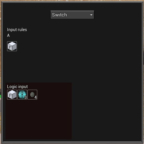
Step 4 – Switch
The logic controller has been connected to a switch. The function has been set to “Switch”. The “Logic input” shows all available signals. I have selected the stainless steel fermenter for the input. It will have a value of 0 or 1 based on the logic circuit 1 output.
Final Result
The switch will be turned on or off depending on if there are greater than 3 items of coke in the stone chest.
Hope you enjoy the post for Evospace Logic Devices Information New Version, If you think we should update the post or something is wrong please let us know via comment and we will fix it how fast as possible! Thank you and have a great day!
- Check All Evospace Posts List


Leave a Reply