Intro and Basic Map and Compass Tasks
This guide explains how to perform land navigation without a GPS, using a map and compass, a skill often unused by vanilla Arma players.
How to Toggle the Map and Compass
Refer to the following resources for accurate information:
- In-game Field Manual
- Controls settings
In order to use the map or compass, the respective item must be in the appropriate slot of the player’s inventory. A GPS or UAV Terminal can substitute for a map.
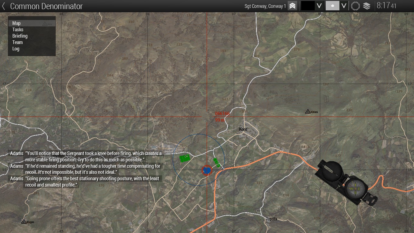
By default on a US Keyboard, the map is toggled using the “M” key. On the top-right of the map UI, there are controls for some functions of the map. Tooltips explain the functionality of the buttons.
These controls allow the player to:
- Select the colour of new map markers placed by the player
- Select the symbol of map markers placed by the player
- Center the map on the player’s position at a fixed level of zoom (Move map to player position)
- Show/hide satellite imagery layer (Toggle map textures)
The compass can be flashed by holding the “K” key. The compass is toggled by double-tapping the “K” key. The compass is a simplified version of the lensatic compass used by the US military. Here is a diagram of such a compass from US Army field manual FM 3-25.26:
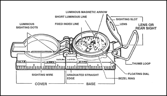
Relevant features in Arma include the fixed index line along the base; the sighting wire, and luminous sighting dots on the cover; and the dial inside the base.
When viewing the map, the compass will appear on top of it. It can be enlarged and shrunk by double-clicking it.
How to Read the Compass
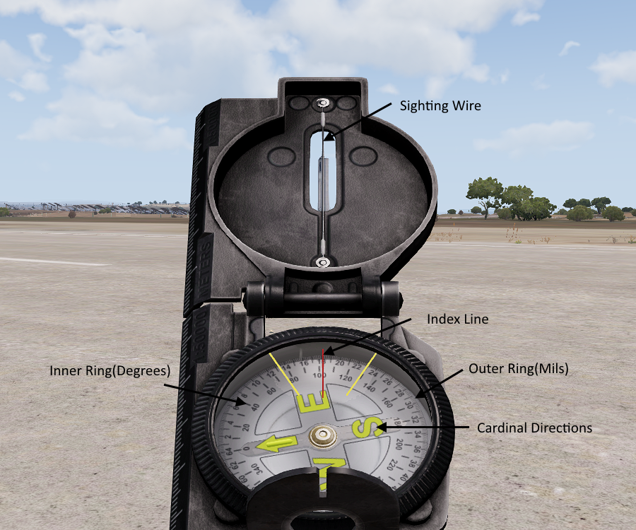
The compass is always pointed in the same direction as the player’s view.
There are two rings of numbers on the dial of the compass:
- The outer ring shows the azimuth (angle from North, also referred to as bearing) in milliradians (mils). This is not used in Arma.
- The inner ring shows the azimuth in degrees.
- Yellow letters signify the cardinal directions (North, East, South, and West clockwise). An arrow substitutes the “N” for north.
To use the compass:
- Rotate yourself in the desired direction. You may use the sighting wire and luminous sighting dots to orient yourself precisely.
- Read the azimuth in degrees or the cardinal direction under the fixed index line.
Read the azimuth in degrees with a leading zero. For example, “bearing 010” indicates an azimuth 10 degrees east of North.
Under duress it is more convenient to communicate the azimuth using cardinal directions than in degrees. For example, when under fire from bearing 045, one may say: “Contact, 75 metres, northeast.”
When using the map, the compass continues to be pointed in the same direction as the player’s view. The top of the map is always pointed towards the north. There is no magnetic declination in Arma. Magnetic north is the same as true north.
How to Read the Map and Grid Coordinates
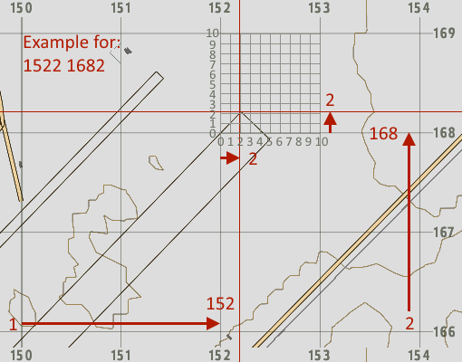
To locate a point on the map using grid coordinates:
- Find the grid line corresponding to the longitude. Its number corresponds to the first half of the grid coordinate. Read from left to right.
- Find the grid line corresponding to the latitude. Its number corresponds to the second half of the grid coordinate. Read from bottom to top.
- Concatenate the second number to the end of the first number. As an example, if you found a longitude of 152 and a latitude of 168, the final coordinate would be 152168.
Alternatively, text adjacent to the cursor shows the elevation and grid coordinates of the position under the cursor.
The map in Arma uses a grid system. The grid system allows positions on the map to be communicated by their grid coordinates. Each line of the grid is numbered.
Depending on zoom level, the grid can have a precision of 10km (two-digit grid), 1km (four-digit grid), or 100m (six-digit grid). Each digit represents a level of precision. For example, the coordinate 152168 is more precise than the coordinate 1516, even though the person communicating these coordinates may be referring to the same place.
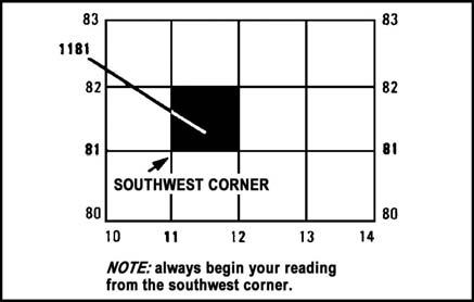
The first half of a grid coordinate is its longitude (easting), which is its position along the x-axis of the map. A larger number indicates a greater distance east. Similarly, the second half of a grid coordinate is its latitude (northing), which is its position along the y-axis of the map. A larger number indicates a greater distance north. The grid square corresponding to a grid coordinate is to the northeast of the intersecting lines, as illustrated in US Army Soldier’s Manual of Common Tasks STP-21-1-SMCT:
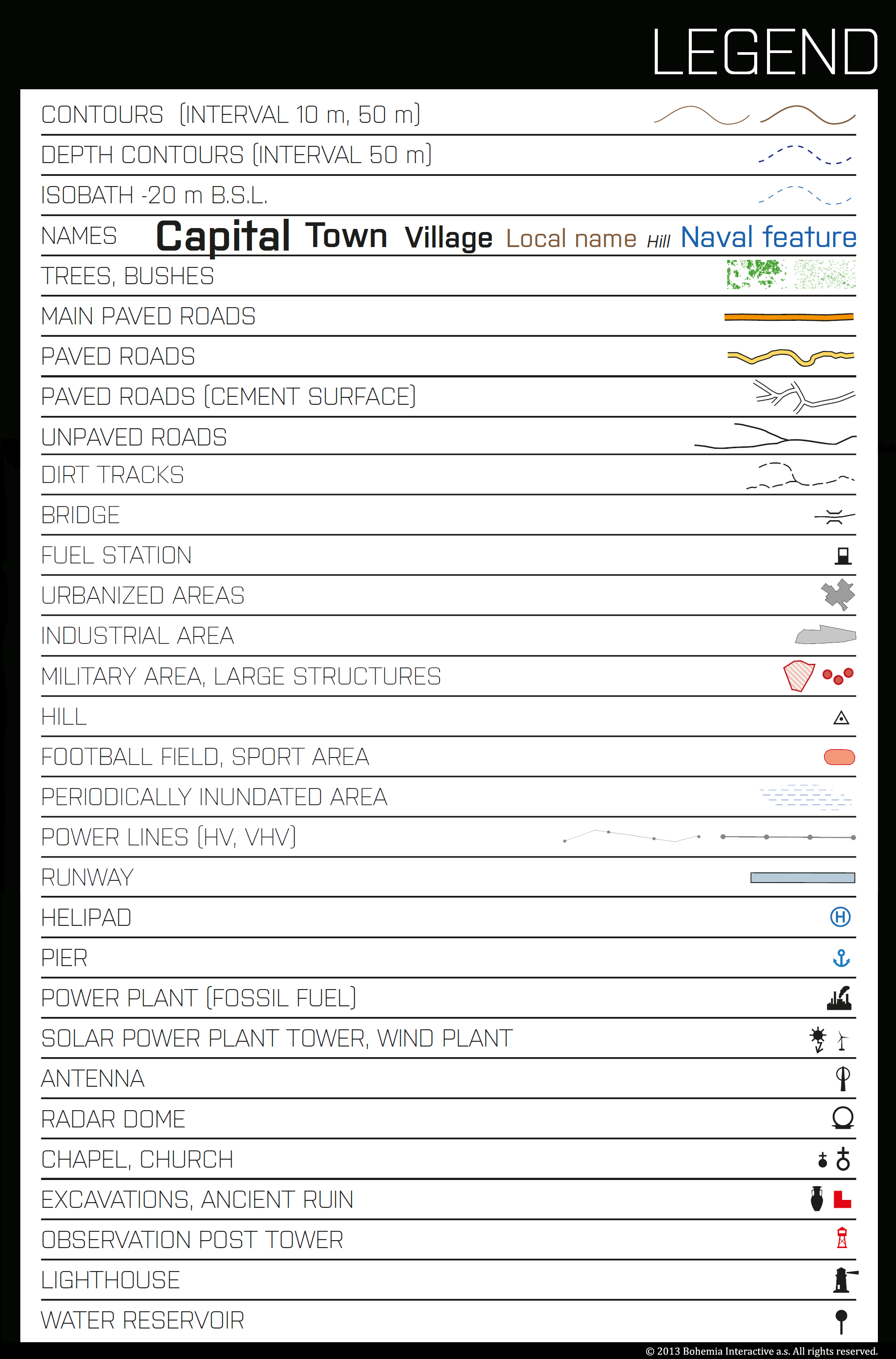
There is no legend for the map in Arma 3, however, aside from NATO military symbols, the symbology of the map should be obvious for people of most cultures. The following legend was created early in the game’s development and may no longer be accurate:
Contour lines are brown non-intersecting lines on the map which form various shapes conforming to the terrain. Contour lines are valuable for understanding the shape of the terrain. Contour lines are more obvious when the satellite layer is turned off. More information on using contour lines can be found in the Terrain Features section of this guide.
The summits of hills and other elevated points may be marked with numbers. These numbers indicate the elevation above sea level of the point. They may be referred to in communications by these numbers. For example, the hill northwest of Topolia, Altis which has a summit at the elevation of 114 ASL may be referred to as “Hill 114”.
How to Draw Lines and Markers
Map markers can be placed by double-clicking on the position where the desired marker is to be placed. One may then input a label and select the radio channel on which the marker is seen. The marker symbol may be changed using the up/down arrow keys or the dropdown menu on the top-right. The marker colour may be changed by holding shift while using the up/down arrow keys. Markers can be deleted by hovering over the marker and using the Delete key.
Freeform lines can be drawn by holding Ctrl while drawing the line. Straight lines can be drawn by holding Ctrl and Shift simultaneously while drawing the line.
Further Reading and Credits
Much of the content of this guide is covered in the Prologue campaign (tutorial/Bootcamp) mission Diplomatic Relations. Similar guides include:
- Dslyecxi TTP3, which covers most of this section: https://ttp3.dslyecxi.com/basic_infantry_skills/#usage-of-the-map
- Map Reading, Map Tools and Markers – Reading and using the Arma 3 Map #Arma3 by 1st Air Assault, which also covers the ACE3 mod: https://www.youtube.com/watch?v=YBrmLlxgOnc
- Land Navigation by Thendash of Clear Backblast, which also covers the ACE3 mod: https://wiki.clearbackblast.com/guides:land_nav
This guide contains content and images from Thendash of Clear Backblast, which are licenced under CC Attribution-Share Alike 4.0 International.
Terrain Features
For tactical and navigational purposes, it is important to recognize terrain features.
Contour Lines
Contour lines are brown non-intersecting lines on the map which form various shapes conforming to the terrain. Contour lines are more obvious when the satellite layer is turned off. Contour lines are valuable for understanding the shape of the terrain. Contour lines which are close together indicate steep terrain. Contour lines which are far apart indicate flat terrain.
Here is a diagram of contour lines from US Army field manual FM 3-25.26:
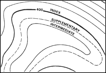
Every fifth contour line is bold. These contour lines are known as index contour lines. Other contour lines are known as intermediate contour lines. Here are contour lines as seen in-game:
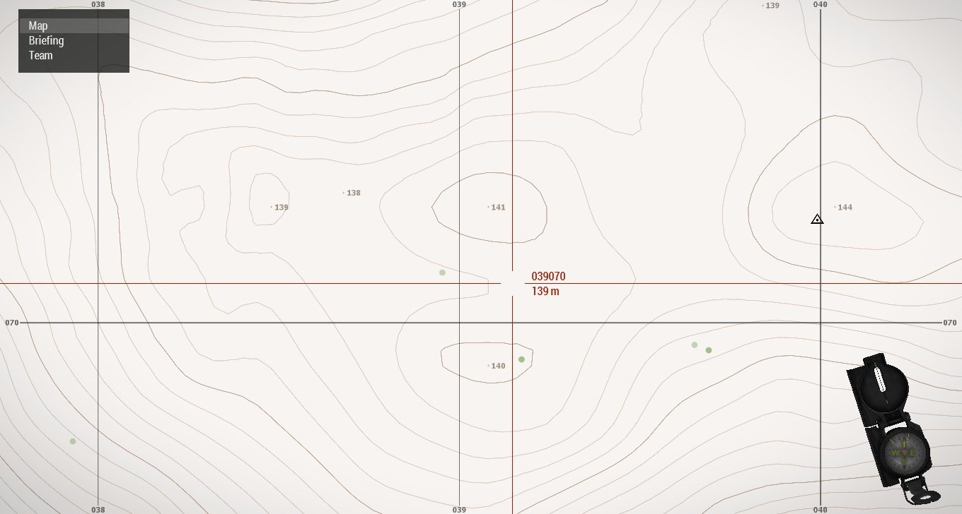
A fixed amount of change in elevation occurs between contour lines. For example, there may be a change of 1m in elevation between the contour lines. The amount of change in elevation between contour lines is known as the contour interval. Despite having a variable contour interval depending on zoom level, in vanilla Arma, there is no scale indicating the contour interval.
The summits of hills and other elevated points may be marked with numbers. These numbers indicate the elevation above sea level of the point. They may be referred to in communications by these numbers. For example, the hill northwest of Topolia, Altis which has a summit at the elevation of 114 ASL may be referred to as “Hill 114”.
Terrain Features
The US Army has produced a video on identifying terrain features:

The US Army categorizes terrain features into five major features, and three minor features.
Here is a table of the five major features with accompanying illustrations from US Army Soldier’s Manual of Common Tasks STP-21-1-SMCT:
| Name | Description | Map Symbol Description | Illustration |
| Hill | A point or small area of high ground from which the ground slopes down in all directions | Contour lines forming concentric circles | 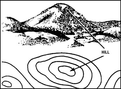 |
| Ridge | A line of high ground with height variations along its crest. | Contour lines forming a “U” or “V.” Closed end points away from high ground. | 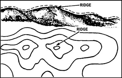 |
| Valley | Reasonably level ground bordered on three sides by higher ground. Decent maneuver room. The side in between two of the sides with higher ground which also has higher ground may not be obvious. Contains a stream flowing downhill from higher ground | Contour lines form “U” or “V.” Contour lines parallel a stream before crossing at the closed end of the “U” or “V.” The closed end of the contour lines point uphill or upstream. | 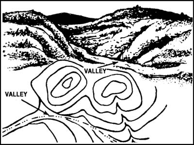 |
| Saddle | A dip or low-point along a ridge or crest; either lower ground between two hilltops or a break in a level crest. | Hourglass shape | 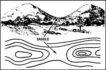 |
| Depression | Low point or hole in the ground. | Closed contour lines. Has tick marks pointing towards lower ground on US Army maps (not seen in-game). | 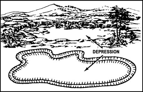 |
Here is a similar table for the three minor features:
| Name | Description | Map Symbol Description | Illustration |
| Draw | Similar to a valley, but with low maneuver room. Ground is not level, may have intermittent streams. Ground slopes upwards on the sides and towards the head of the draw (high ground). | Contour lines are “V” shaped and point towards the head of the draw (high ground). | 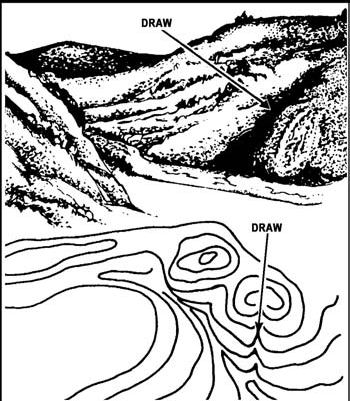 |
| Spur | A short continuously sloping line of higher ground jutting out from the side of a ridge. Often formed by parallel streams cutting draws down a ridge. | Contour lines forming a “U” or “V.” Closed end points away from high ground. | 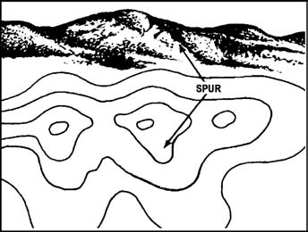 |
| Cliff | Vertical or nearly vertical slope. | Contour lines very close together. May be depicted as a single line with tick marks pointing to lower ground on US Army maps (not seen in-game). | 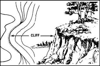 |
STP-21-1-SMCT suggests using the hand as an instructional aid for remembering common terrain features:
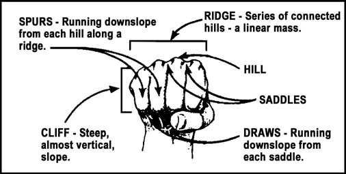
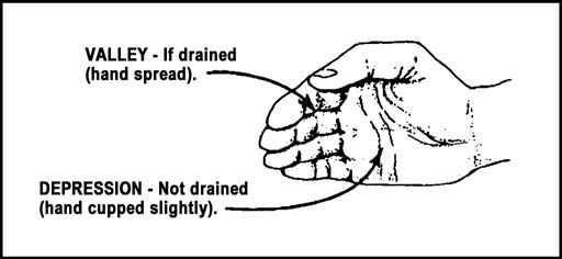
Other Features
Other features on a map may also be useful. Manmade features include:
- Roads
- Trails
- Runways
- Power lines
- Rail tracks
- Prominent structures
- Religious buildings
Map and Compass Line Drawing Tasks
There is no protractor in vanilla Arma. There is some amount of space extending from the graduated straight edge of the compass on the map which is still considered to be part of the compass. This makes it difficult to draw lines based on an azimuth or measure angles. Further, lines can only be drawn with endpoints at discrete increments, causing inaccuracy when using any of the techniques in this guide.
Drawing a Line Based on the Azimuth Displayed by the Map Compass
To draw a line based on the straight edge of the compass, which will always point towards direction of the direction of the view of the player while in the map, use the following workaround:
- Place map markers at the ends of the straight edge of the compass. The dot marker is the most useful for this.
- Draw a line intersecting with those markers.
- Delete the markers if desired.
It may be helpful to enlarge the map compass.
Determining Grid Azimuth
To determine the azimuth of a line on the map (determining grid azimuth), use the following workaround:
- Place the map compass (the hinge between the cover and the base) over the line.
- Exit the map and rotate the player
- Return to the map and compare the straight edge of the map compass to the line, moving the compass if necessary. If they are not parallel, repeat the previous steps.
- When the straight edge is parallel to the line, exit the map, and read the azimuth from the compass. This is the grid azimuth.
It may be helpful to enlarge the map compass. Be careful to ensure the map compass is pointing in the direction from the starting point to the ending point. If the compass is pointed in the opposite direction, the back-azimuth is obtained.
Calculating Back-Azimuth
The US Army has produced a video on calculating back-azimuth:

Back-azimuth is the azimuth corresponding to the opposite direction of another azimuth. It can be calculated in degrees using the following formula:
((Azimuth + 180) % 360) = Back-Azimuth
or
If the azimuth is under 180 degrees, (Azimuth + 180) = Back-Azimuth
If the azimuth is over 180 degrees, (Azimuth – 180) = Back-Azimuth
Locating an Unknown Position Using a Map and Compass
Intersection/resection are similar techniques for locating an unknown position on a map using two or more known positions and azimuths between them and the unknown position. They involve drawing lines from the known positions and finding the intersection of the lines.
Terrain Association
The US Army has produced a video on terrain association:

Terrain association is the act of correlating visible features with positions on the map. This should come naturally and improve with experience. It can be performed to find known locations for further use in intersection and resection.
Features to consider when performing terrain association include and are not limited to:
- Obvious features
- Shape, elevation, and steepness of terrain
- Positions of features relative to each other
- Bodies of water, vegetation, structures
Intersection
The US Army has produced a video on intersection:

Intersection is the technique used when the azimuths from the known positions to the unknown positions are known.
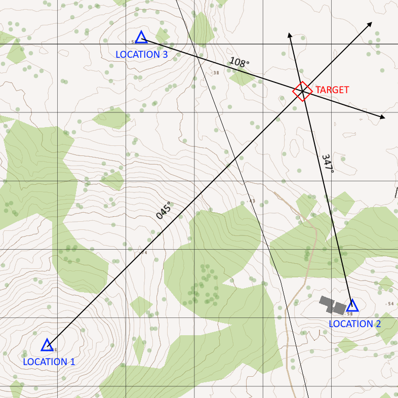
- Draw a line from the first known position with the azimuth to the unknown position
- Repeat for all the known positions
- The intersection of the lines is the unknown position
Resection
The US Army has produced a video on resection:

Resection is the technique used when the azimuths from the unknown position to the known positions are known. This technique was demonstrated in the Bootcamp mission Diplomatic Relations.
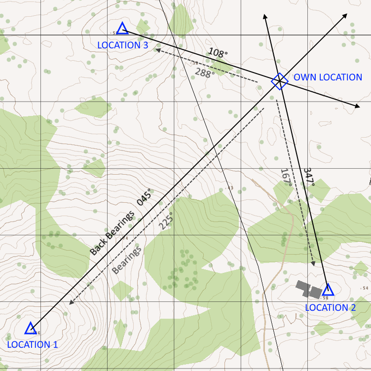
- Draw a line from the first known position to the unknown position with the back-azimuth from the unknown position to the known position as its azimuth
- Repeat for all the known positions
- The intersection of the lines is the unknown position
If the unknown feature is along a known linear feature such as a road, the intersection of the line from a single known position to the linear feature may be used. The line from the known position should have the back-azimuth as in ordinary resection.
Movement and Navigation
The US Army has produced a video on navigation:

Planning a Route
- Mark start and stop points
- Mark checkpoints, between which travel will be performed using terrain association or dead reckoning
- Mark boundary features around the route as necessary
- If desired, estimate distances between the checkpoints. When following the route, paces may be counted to measure distance travelled.
Considerations when planning a route include:
- Travel time
- Travel distance
- Maneuver room required
- Traffic
- Stamina
- Tactical considerations
- Ease of support
- Enemy locations
- Availability of good landmarks
- Availability of good checkpoints
Terrain usually prohibits moving in a straight line. Find and mark features (boundary features) around the route, crossing which indicates you have strayed from the route.
Tactical considerations such as cover and concealment are important. Skylining, and crossing open/dangerous areas such as roads, streams, and open fields may be convenient, but are also dangerous. Using excessively difficult terrain may result in becoming lost, being slow, or getting tired.
While Moving
It is important not to be distracted by navigation such that awareness and security are compromised. This is most easily accomplished in a group by delegating security to other members of the group while one member of the group navigates.
Dead reckoning and terrain association are the methods used for navigation while moving. It is not possible to measure distances in vanilla Arma using a map and compass, thus navigation cannot rely on pace counts.
Dead Reckoning
Navigation by dead reckoning involves selecting an azimuth, then using a compass, moving in a straight line following the azimuth.
A route using dead reckoning may use steering marks, which are checkpoints one aims towards when dead reckoning.
Terrain Association
Navigation by terrain association involves navigating using features such as roads, rivers, and hills as landmarks or checkpoints. This is the most obvious method of navigation.
Linear features such as roads can be used as “handrails” which are followed in parallel.
Linear features can also be used as checkpoints to be crossed. If linear features cannot be used, large changes in elevation can be used.
Bypassing Obstacles
Greybeard has produced a guide on bypassing danger areas:
https://steamcommunity.com/sharedfiles/filedetails/?id=2448095329
The following diagram from US Army field manual FM 3-21.71 illustrates methods of bypassing small danger areas:
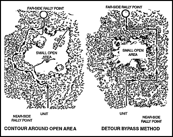
Contour
This technique involves following the edges of the obstacle until one returns to the axis of travel.
Detour
This technique is more expedient for dead reckoning navigation.
- Travel perpendicular from the axis of travel until the obstacle is outflanked
- Travel parallel to the axis of travel to the end of the obstacle
- Travel perpendicular to the axis of travel until you have returned to the axis of travel
- Continue along the axis of travel
Hope you enjoy the post for Arma 3 Basic LandNav, If you think we should update the post or something is wrong please let us know via comment and we will fix it how fast as possible! Thank you and have a great day!
- Check All Arma 3 Posts List


Leave a Reply